
Page 209 - Failure Analysis Case Studies II
P. 209
1 94
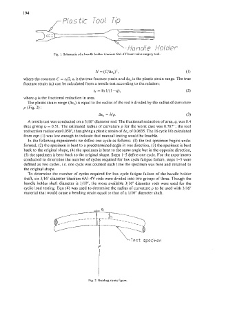
,-Plastic Tool Tip
y., Hondie Holder
Fig. 1. Schematic of a handle holder titanium 6AI4V heart valve surgery tool
N = (C/AeP)’, (1)
where the constant C = 42, ef is the true fracture strain and is the plastic strain range. The true
fracture strain (EJ can be calculated from a tensile test according to the relation :
ef = In l/(l -q), (2)
where q is the fractional reduction in area.
The plastic strain range (AE~) equal to the radius of the rod h divided by the radius of curvature
is
p (Fig. 2) :
= h/p. (3)
A tensile test was conducted on a 3/16 diameter rod. The fractional reduction of area, q, was 0.4
thus giving ef = 0.51. The estimated radius of curvature p for the worst case was 0.787”; the tool
rod section radius was 0.050, thus giving a plastic strain of Aep of 0.0635. The 16 cycle life calculated
from eqn (1) was low enough to indicate that manual testing would be feasible.
In the following experiments we define one cycle as follows : (I) the test specimen begins unde-
formed, (2) the specimen is bent to a predetermined angle in one direction, (3) the specimen is bent
back to the original shape, (4) the specimen is bent to the same angle but in the opposite direction,
(5) the specimen is bent back to the original shape. Steps 1-5 define one cycle. For the experiments
conducted to determine the number of cycles required for low cycle fatigue failure, steps 1-5 were
defined as two cycles, Le. one cycle was counted each time the specimen was bent and returned to
the original shape.
To determine the number of cycles required for low cycle fatigue failure of the handle holder
shaft, six 3/16” diameter titanium 6A14V rods were divided into two groups of three. Though the
handle holder shaft diameter is 1/10, the more available 3/16” diameter rods were used for the
cyclic load testing. Eqn (4) was used to determine the radius of curvature p to be used with 3/16“
material that would cause a bending strain equal to that of a 1/10” diameter shaft.
fY-Tq
--------
-
--
LTest specimen
P
Fig. 2. Bending strain figure.