
Page 222 - Failure Analysis Case Studies II
P. 222
207
- lSO B
h
- 100
rz
- 50
.o
I
I
1 I
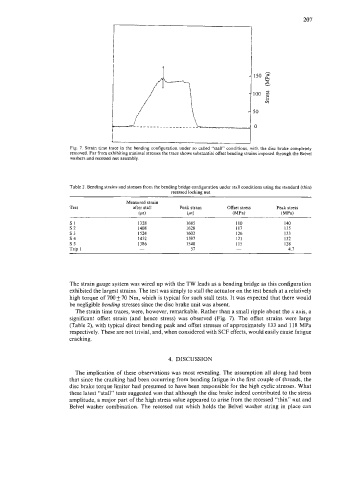
Fig. 7. Strain time trace in the bending configuration under so called “stall” conditions, with the disc brake completely
removed. Far from exhibiting minimal stresses the trace shows substantial offset bending strains imposed through the Belvel
washers and recessed nut assembly.
Table 2. Bending strains and stresses from the bending bridge configuration under stall conditions using the standard (thin)
recessed locking nut
Measured strain
Test after stall Peak strain Offset stress Peak stress
(pa) (pa) (MPa) (MPa)
SI 1328 1685 I10 I40
s2 1408 1628 I17 135
53 1524 1602 126 133
s4 1452 1597 121 132
s5 1386 1540 115 128
Trip 1 - 57 - 4.7
The strain gauge system was wired up with the TW leads as a bending bridge as this configuration
exhibited the largest strains. The test was simply to stall the actuator on the test bench at a relatively
high torque of 700 & 70 Nm, which is typical for such stall tests. It was expected that there would
be negligible bending stresses since the disc brake unit was absent.
The strain time traces, were, however, remarkable. Rather than a small ripple about the x axis, a
significant offset strain (and hence stress) was observed (Fig. 7). The offset strains were large
(Table 2), with typical direct bending peak and offset stresses of approximately 133 and 118 MPa
respectively. These are not trivial, and, when considered with SCF effects, would easily cause fatigue
cracking.
4. DISCUSSION
The implication of these observations was most revealing. The assumption all along had been
that since the cracking had been occurring from bending fatigue in the first couple of threads, the
disc brake torque limiter had presumed to have been responsible for the high cyclic stresses. What
these latest “stall” tests suggested was that although the disc brake indeed contributed to the stress
amplitude, a major part of the high stress value appeared to arise from the recessed “thin” nut and
Belvel washer combination. The recessed nut which holds the Belvel washer string in place can