
Page 220 - Failure Analysis Case Studies II
P. 220
205
I
I
I
1 - 100
1
1
1
1
I
I h
1 - d
1 . 50
1
0
I
(b) Zl
10
t
I
I
I
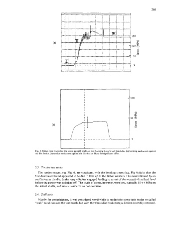
3.3. Torsion test series
The torsion traces, e.g. Fig. 6, are consistent with the bending traces (e.g. Fig qa)) in that the
first downward trend appeared to be due to take up of the Belvel washers. This was followed by an
oscillation as the disc brake torque limiter engaged leading to arrest of the wormshaft at fixed level
before the power was switched off. The levels of stress, however, were low, typically 55+4 MPa on
the actual shafts, and were considered as not excessive.
3.4. Stall tests
Mostly for completeness, it was considered worthwhile to undertake some tests under so called
"stall" conditions on the test bench, but with the whole disc brake torque limiter assembly removed.