
Page 223 - Failure Analysis Case Studies II
P. 223
208
effectively apply a bending stress to the shaft through the motor housing, which carries the load of
the Belvel washers through the main bearing (Fig. 2).
If the Belvel washer assembly string or the recessed nut were to apply anything but absolutely
symmetric loading, then there could be a significant bending stress developed in the shaft. The
question of how well the recessed thin nut located on the thread became important. Since the
recessed nut in question for the tests had a relatively loose tolerance, on the one hand, and only
engaged less than two threads on the other, it was possible that the nut may have located in a non
symmetrical position on the shaft-especially under load and under the influence of imperfect Belvel
washers, which themselves exhibit a loose fit. The thin nut could effectively “rattle” on the shaft.
Such poor location of the nut could result in a bending stress component to the shaft, especially
under high torque, rapid stall conditions.
In view of this somewhat unexpected finding, it was decided to test the concept (Le. that the high
bending stresses in the shaft were caused by the seating of the Belvel washer/thin nut combination),
by replacing the thin nut with one very much longer. The tolerance and thread details were still the
same, but with a recessed nut of length 28 mm and engaged thread length of 8 threads (as opposed
to approximately 4 mm long and nearly 2 engaged threads), the capacity for the long nut not sitting
squarely on the shaft was substantially reduced. In addition, a further 28 mm long nut was
manufactured, but with a deliberate oblique face (2 degree offset) to simulate the thin nut under
non axisymmetric location.
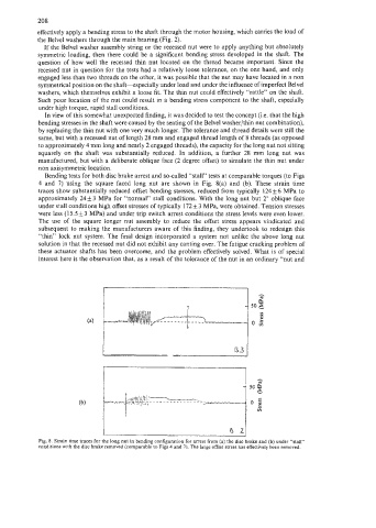
Bending tests for both disc brake arrest and so-called “stall” tests at comparable torques (to Figs
4 and 7) using the square faced long nut are shown in Fig. 8(a) and (b). These strain time
traces show substantially reduced offset bending stresses, reduced from typically 124 f. 6 MPa to
approximately 24 & 3 MPa for “normal” stall conditions. With the long nut but 2” oblique face
under stall conditions high offset stresses of typically 172 k 3 MPa, were obtained. Tension stresses
were less (15.5+3 MPa) and under trip switch arrest conditions the stress levels were even lower.
The use of the square longer nut assembly to reduce the offset stress appears vindicated and
subsequent to making the manufacturers aware of this finding, they undertook to redesign this
“thin” lock nut system. The final design incorporated a system not unlike the above long nut
solution in that the recessed nut did not exhibit any canting over. The fatigue cracking problem of
these actuator shafts has been overcome, and the problem effectively solved. What is of special
interest here is the observation that, as a result of the tolerance of the nut in an ordinary “nut and
B3 I
Fig. 8. Strain time traces for the long nut in bending configuration for arrest from (a) the disc brake and (b) under “stall”
conditions with the disc brake removed (comparable to Figs 4 and 7). The large offset stress has effectively been removed.