
Page 228 - Failure Analysis Case Studies II
P. 228
213
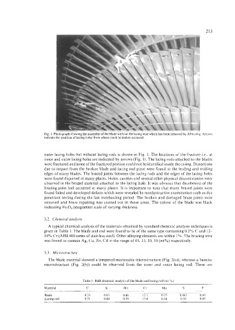
Fig. 1. Photograph showing the assembly of the blade without the lacing wire which has been removed by debrazing. Arrows
indicate the position of lacing holes from where crack initiation occurred.
outer lacing holes but without lacing rods is shown in Fig. 1. The locations of the fracture Le., at
inner and outer lacing holes are indicated by arrows (Fig. 1). The lacing rods attached to the blades
were fractured and some of the fractured portion could not be identified inside the casing. Distortions
due to impact from the broken blade and lacing rod piece were found at the leading and trailing
edges of many blades. The brazed joints between the lacing rods and the edges of the lacing holes
were found disjoined at many places. Holes, cavities and several other physical discontinuities were
observed in the brazed material attached to the lacing hole. It was obvious that decohesion of the
brazing joint had occurred at many places. It is important to note that many brazed joints were
found failed and developed defects which were revealed by nondestructive examination such as dye
penetrant testing during the last overhauling period. The broken and damaged braze joints were
removed and braze repairing was carried out in those areas. The colour of the blade was black
indicating Fe,O, (magnetite) scale of varying thickness.
3.2. Chemical analysis
A typical chemical analysis of the materials obtained by standard chemical analysis techniques is
given in Table 1. The blade and rod were found to be of the same type containing 0.2% C and 12-
14% Cr (AIS1 400 series of stainless steel). Other alloying elements are within 1 %. The brazing wire
was found to contain Ag, Cu, Zn, Cd in the range of 65, 15, 10, 10 (wt%) respectively.
3.3. Microstructure
The blade material showed a tempered martensitic microstructure (Fig. 2(a)), whereas a bainitic
microstructure (Fig. 2(b)) could be observed from the inner and outer lacing rod. These are
Table 1. Bulk chemical analysis of the blade and lacing rod (wt %)
Material C Si Mn Cr Mo S P
Blade 0.23 0.83 0.46 12.1 0.25 0.007 0.03
Lacing rod 0.21 0.40 0.50 13.4 0.14 0.01 0.05