
Page 230 - Failure Analysis Case Studies II
P. 230
215
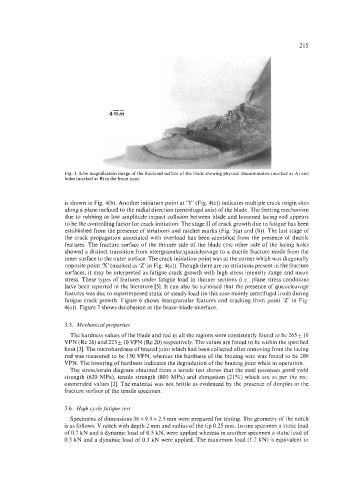
Fig. 3. Low magnification image of the fractured surface of the blade showing physical discontinuities (marked as A) and
holes (marked as B) in the braze joint.
is shown in Fig. 4(b). Another initiation point at ‘I” (Fig. 4(c)) indicates multiple crack origin sites
along a plane inclined to the radial direction (centrifugal axis) of the blade. The fretting mechanism
due to rubbing or low amplitude impact collision between blade and loosened lacing rod appears
to be the controlling factor for crack initiation. The stage I1 of crack growth due to fatigue has been
established from the presence of striations and ratchet marks (Fig. 5(a) and (b)). The last stage of
the crack propagation associated with overload has been identified from the presence of ductile
features. The fracture surface of the thinner side of the blade (the other side of the lacing hole)
showed a distinct transition from intergranular/quasicleavage to a ductile fracture mode from the
inner surface to the outer surface. The crack initiation point was at the corner which was diagonally
opposite point ‘X’ (marked as ‘Z’ in Fig. 4(a)). Though there are no striations present in the fracture
surfaces, it may be interpreted as fatigue crack growth with high stress intensity range and mean
stress. These types of features under fatigue load in thinner sections (Le., plane stress condition)
have been reported in the literature [5]. It can also be surmised that the presence of quasicleavage
features was due to superimposed static or steady load (in this case mainly centrifugal load) during
fatigue crack growth. Figure 6 shows intergranular features and cracking from point ‘Z in Fig.
4(a)). Figure 7 shows decohesion at the braze-blade interface.
3.5. Mechanicalproperties
The hardness values of the blade and rod in all the regions were consistently found to be 265 & 10
VPN (Rc 26) and 225 10 VPN (Rc 20) respectively. The values are found to be within the specified
limit [3]. The microhardness of brazed joint which had been collected after removing from the lacing
rod was measured to be 150 VPN, whereas the hardness of the brazing wire was found to be 200
VPN. The lowering of hardness indicates the degradation of the brazing joint while in operation.
The stress/strain diagram obtained from a tensile test shows that the steel possesses good yield
strength (620 MPa), tensile strength (800 MPa) and elongation (21%) which are as per the rec-
ommended values [3]. The material was not brittle as evidenced by the presence of dimples in the
fracture surface of the tensile specimen.
3.6. High cycle fatigue test
Specimens of dimensions 36 x 9.5 x 2.5 mm were prepared for testing. The geometry of the notch
is as follows: V notch with depth 2 mm and radius of the tip 0.25 mm. In one specimen a static load
of 0.7 kN and a dynamic load of 0.5 kN, were applied whereas in another specimen a static load of
0.5 kN and a dynamic load of 0.3 kN were applied. The maximum load (1.2 kN) is equivalent to