
Page 235 - Failure Analysis Case Studies II
P. 235
220
4n’MrN;
-~
-
A ’
where M = mass, V = surface velocity, r = radius from the rotation axis, A = area of cross section,
N, = turbine speed in rps. Here we have calculated the centrifugal stress at the root point (r = 0.5
m), middle point (r = 0.75 m), and near the inner (r = 0.8 m) and outer lacing hole (r = 0.95 m) of
the blade. The blade geometry is tapered and the cross-sectional area is a decreasing function from
the root point to the tip of the blade. Similarly, M is also decreasing from the root of the blade to
the tip whereas the other parameters, V and r are an increasing function from root to tip of blade.
M is estimated to be 2.5 kg at the root, 0.8 kg at the middle, and 0.5 kg at the inner and 0.1 kg at
the outer lacing hole. The approximate cross-sectional area at those points have been calculated to
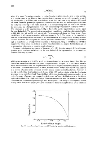
be 880, 480, 400, 160 and 96 mm2 respectively. The stresses as calculated are found to vary from
140 MPa to 59 MPa at various points, which are shown in Fig. 9. The stresses at the inner lacing
hole and outer lacing hole are estimated to be 100 MPa and 60 MPa respectively. It is important to
consider that when the braze joints are broken, the stress concentration at those points could be as
high as three times the average values computed at those points, rising to 300 MPa and 180 MPa
respectively. These values can be taken as upper bound estimates and implies that the holes can act
as strong stress raisers and as potential crack originators.
The stress variation due to a change of frequency of f 5 Hz from the value of 50 Hz (which can
be taken as the maximum variation) near the inner lacing hole during operation, can be calculated
from the following equation:
2oAN,
ACT=-
Ns ’
which gives the value as f20 MPa, which can be experienced by the system time to time. Though
these stress values have not been calculated by rigorous stress analysis, the values can be taken as
upper bound estimates from the simplified calculation which helps to understand the stress patterns
in the blades. Thus from the low value of stress, it can be realized that the material will resist fracture
in a normal situation unless corrosion or other causes become controlling factors. However, it
should be noted that this fluctuation of stresses of 20 MPa makes a cycle within the load cycle
generated by the centrifugal load. Thus, the blade will be experiencing an irregular or random stress
cycle. Corrosion effects were not observed on the fracture surface of the blades except in the thinner
region of the blade. For a high cycle fatigue failure such as the case here, the maximum stress level
can be low and far below the yield strength level. In the present case the cyclic loading had a chance
to play a role because the brazed joint gave way at many places making the blade act as cantilever
1
’ 0.3 0.5 . 017 019
0.1
Relative blade length
-
Fig. 9. Pattern of centrifugal stresses in an LP blade during operation at SO Hz frequency.