
Page 237 - Failure Analysis Case Studies II
P. 237
222
PN
f=- (4)
120’
where f = frequency (Hz), P = no. of poles (it is 2 in the present design of turbogenerator) and
N = the speed of the turbogenerator and turbine (rpm). It can be understood from eqn (4) that f
becomes equal to turbine speed if N is expressed in rpm and Pis 2. This relation helps one to realize
how the turbine speed is related to the frequency of the grid. Since the number of poles is constant,
frequency variation controls the variation of the turbine speed. In the grid system the frequency will
remain at 50 Hz when the input power and the output power of the system are in a balanced state.
Any variation in the system affects the frequency and thus the speed of the machine.
Using Southwell’s theorem we can calculate the natural frequency of the blade for the fundamental
mode for a small vibration from the following relation [12]:
fL =fnZ;+fi
= f :,+ N:, (5)
where fnd = natural frequency of the blade when it is rotating at N, (rps),hs = natural frequency of
the blade tested during a static condition (which is obtained from the test data of the plant as 160-
170 Hz) and fo = excited frequency of the blade when it is rotating with speed N, (rps). The natural
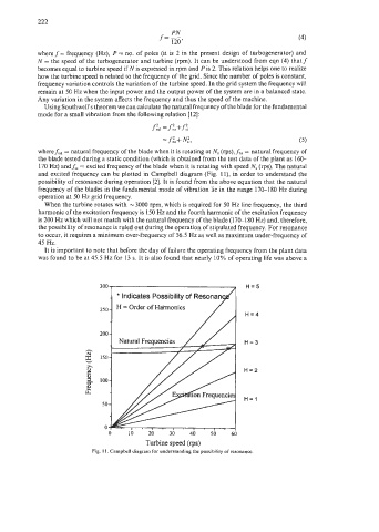
and excited frequency can be plotted in Campbell diagram (Fig. 1 l), in order to understand the
possibility of resonance during operation [2]. It is found from the above equation that the natural
frequency of the blades in the fundamental mode of vibration lie in the range 170-1 80 Hz during
operation at 50 Hz grid frequency.
When the turbine rotates with -3000 rpm, which is required for 50 Hz line frequency, the third
harmonic of the excitation frequency is 150 Hz and the fourth harmonic of the excitation frequency
is 200 Hz which will not match with the natural frequency of the blade (170-180 Hz) and, therefore,
the possibility of resonance is ruled out during the operation of stipulated frequency. For resonance
to occur, it requires a minimum over-frequency of 56.5 Hz as well as maximum under-frequency of
45 Hz.
It is important to note that before the day of failure the operating frequency from the plant data
was found to be at 45.5 Hz for 13 s. It is also found that nearly 10% of operating life was above a
H=5
H=4
H=3
H=2
H=l
Turbine speed (rps)
Fig. I 1. Campbell diagram for understanding the possibility of resonance.