
Page 236 - Failure Analysis Case Studies II
P. 236
22 1
beam. The fluctuation of load pattern affecting bending stress and centrifugal stress and the
resonance vibration from time to time with varying durations create complex alternating or vibratory
stress. This vibratory stress led to fretting between the loosened lacing rod and blade causing fatigue
damage. Thus, the crack initiation became easier from the contact points (‘X’ in Fig. 4(a)) and a
crack propagated through a high cycle fatigue mechanism (HCF).
4.2.1. Fatigue behaviour. The most widely used fatigue crack growth law describing the crack
propagation rate (da/dN) is the Paris equation [IO]:
da
- A(Aqrn, (3)
=
dN
where A and m are material constants and AK is the stress intensity range i.e., K,,, - K,, [K,,, =
maximum stress intensity factor corresponding to the maximum load during the cyclic loading, and
Kmin = minimum stress intensity factor]. K is defined from fracture mechanics as approximately
a&, where n is applied stress and a is the crack length. Crack growth behaviour is controlled
by mean stress and alternating stresses. If the mean stress is high, the stage I and stage 111 crack
propagation rate increases more compared to stage 11. In fact, features due to a static mode of
fracture, i.e., intergranular, quasicleavage and dimples can also be seen on the fracture surface under
fatigue loading.
In the present investigaticn, striations have been observed in the thicker portion of the blades. In
the thinner parts other features such as intergrannular, quasicleavage and dimples have been
observed. Laboratory simulated fatigue testing discussed earlier has also shown the presence of
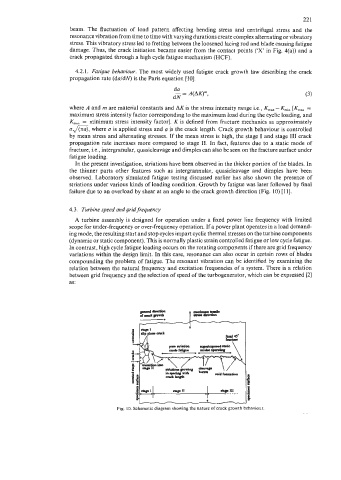
striations under various kinds of loading condition. Growth by fatigue was later followed by final
failure due to an overload by shear at an angle to the crack growth direction (Fig. 10) [ll].
4.3. Turbine speed and grid frequency
A turbine assembly is designed for operation under a fixed power line frequency with limited
scope for under-frequency or over-frequency operation. If a power plant operates in a load demand-
ing mode, the resulting start and stop cycles impart cyclic thermal stresses on the turbine components
(dynamic or static component). This is normally plastic strain controlled fatigue or low cycle fatigue.
In contrast, high cycle fatigue loading occurs on the rotating components if there are grid frequency
variations within the design limit. In this case, resonance can also occur in certain rows of blades
compounding the problem of fatigue. The resonant vibration can be identified by examining the
relation between the natural frequency and excitation frequencies of a system. There is a relation
between grid frequency and the selection of speed of the turbogenerator, which can be expressed (21
as:
Fig. 10. Schematic diagram showing the nature of crack growth behaviour.