
Page 233 - Failure Analysis Case Studies II
P. 233
218
Fig. 6. Fractograph from the site marked as ‘Z in Fig. 4(a) showing the presence of intergranular features. Intergranular
crack is indicated by the arrow head.
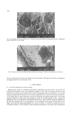
Fig. 7. Decohesion at the braze-blade interface (marked by arrow head). P: blade; Q: corroded portion of the braze.
observe various types of features on fatigue fractured surfaces. This agrees with other investigations
on fatigue reported in the literature [5, 61.
4. DISCUSSION
4.1. Corrosion mechanism of braze material
Brazed ferritic steels are extremely susceptible to interfacial corrosion when a Ag-Cu-Zn-Cd
brazing filler material is used. The conditions conducive to this form of corrosion are that (a) one
member of the joint must be stainless steel, (b) the brazing alloy must be susceptible to this attack
and (c) the joint must be exposed to wet or damp conditions [7]. It is obvious from the environment
of LP zones that all three conditions existed at the lacing wire-blade brazed joint. The brazed
material exhibited numerous pits and micropores which are morphologically similar to plug type
dealloying. This was confirmed by SEM-EDX observations which revealed significant depletion of
Zn from the brazing near to the lacing hole. Cr was detected in the braze material close to the
blade-braze interface suggesting depletion of Cr from the blade. It is difficult to pinpoint the exact
mechanism leading to this interfacial attack although dealloying of the braze with simultaneous