
Page 234 - Failure Analysis Case Studies II
P. 234
~ _ ... . _ ~
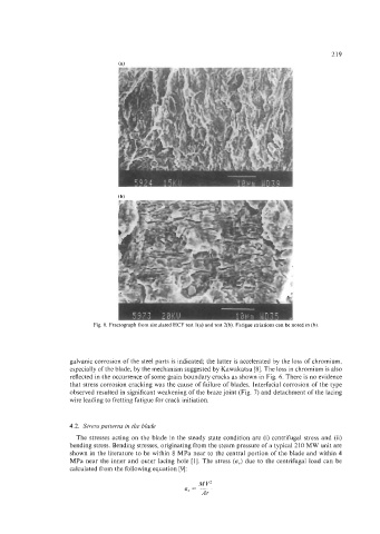
Fig. 8. Fractograph from simulated HCF test l(a) and test 2(b) Fatigue striations can be noted in (b).
galvanic corrosion of the steel parts is indicated; the latter is accelerated by the loss of chromium,
especially of the blade, by the mechanism suggested by Kawakatsu [SI. The loss in chromium is also
reflected in the occurrence of some grain boundary cracks as shown in Fig. 6. There is no evidence
that stress corrosion cracking was the cause of failure of blades. Interfacial corrosion of the type
observed resulted in significant weakening of the braze joint (Fig. 7) and detachment of the lacing
wire leading to fretting fatigue for crack initiation.
4.2. Stresspatterns in the blade
The stresses acting on the blade in the steady state condition are (i) centrifugal stress and (ii)
bending stress. Bending stresses, originating from the steam pressure of a typical 210 MW unit are
shown in the literature to be within 8 MPa near to the central portion of the blade and within 4
MPa near the inner and outer lacing hole [I]. The stress (oc) due to the centrifugal load can be
calculated from the following equation [9]: