
Page 215 - Failure Analysis Case Studies II
P. 215
200
torque switch
\
\ end locking nuts
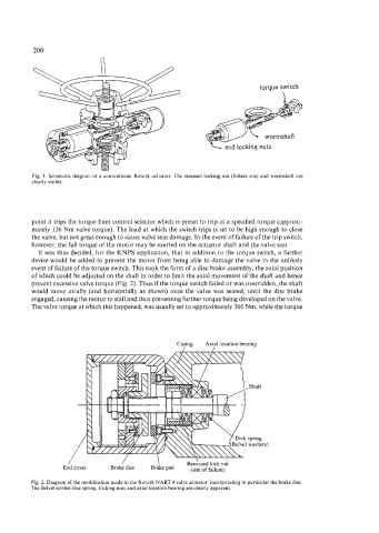
Fig. 1. Schematic diagram of a conventional Rotork actuator. The recessed locking nut (failure site) and wormshaft are
clearly visible.
point it trips the torque limit control selector which is preset to trip at a specified torque (approxi-
mately 136 Nm valve torque). The load at which the switch trips is set to be high enough to close
the valve, but not great enough to cause valve seat damage. In the event of failure of the trip switch,
however, the full torque of the motor may be exerted on the actuator shaft and the valve seat.
It was thus decided, for the KNPS application, that in addition to the torque switch, a further
device would be added to prevent the motor from being able to damage the valve in the unlikely
event of failure of the torque switch. This took the form of a disc brake assembly, the axial position
of which could be adjusted on the shaft in order to limit the axial movement of the shaft and hence
prevent excessive valve torque (Fig. 2). Thus if the torque switch failed or was overridden, the shaft
would move axially (and horizontally as shown) once the valve was seated, until the disc brake
engaged, causing the motor to stall and thus preventing further torque being developed on the valve.
The valve torque at which this happened, was usually set to approximately 366 Nm, while the torque
Casing Axial location bearing
/
,Shaft
spring
washers)
/ / \ Reckssed lock nut
End cover Brake disc Brake pad (site of failure)
Fig. 2. Diagram of the modification made to the Rotork NABT 4 valve actuator, incorporating in particular the brake disc.
The Belvel washer disc spring, locking nuts and axial location bearing are clearly apparent.