
Page 217 - Failure Analysis Case Studies II
P. 217
202
2. EXPERIMENTAL DETAILS
2.1. ShaB system and strain gauging
The requirement of measuring the strains in the vicinity of the first one or two threads, where the
cracking occurred, was not without constraints. If there were to be a bending stress component,
presumably from the disc brake loading unsymmetrically, then a strain gauge located here would
need to be at the same distance from the brake as are the first one or two threads.
To place the strain gauge rosette on the unthreaded portion of the shaft close to this first thread
was not acceptable because the Belvel washers are loated here and they need to slide freely on the
shaft. Similarly the thread root itself cannot be readily straingauged because it is too small an area
and would be susceptible to stress concentration effects (SCF). Consequently the first three threads
were ground off an actuator shaft with the corners radiused, yielding a total smooth shaft length of
9.5 mm. The shaft diameter was reduced in this region to 15.50 mm since the only wormshaft
actuator available was one that had already exhibited some limited fatigue cracking at the first
thread. It was thus necessary to grind the diameter down to below the fatigue crack depth (effectively
removing it) and for this it was necessary to go to a diameter of 15.50 mm. After grinding, the shaft
was non destructively inspected rigorously, using magnetic particle inspection (MPI) techniques
which confirmed that this reduced section, and indeed the rest of the threads, were free of any
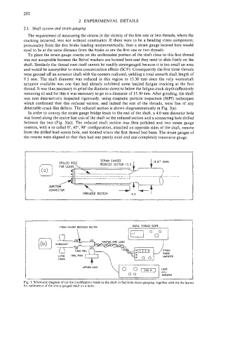
detectable crack like defects. The reduced section is shown diagrammatically in Fig. 3(a).
In order to convey the strain gauge bridge leads to the end of the shaft, a 4.0 mm diameter hole
was bored along the centre line axis of the shaft to the reduced section and a connecting hole drilled
between the two (Fig. 3(a)). The reduced shaft section was then polished and two strain gauge
rosettes, with a so called O", 45", 90" configuration, attached on opposite sides of the shaft, remote
from the drilled lead access hole, and located where the first thread had been. The strain gauges of
the rosette were aligned so that they had one purely axial and one completely transverse gauge.
OICITAL STORAGE SCOPE
STRAN CAWD RECESKD SECTION
I
n \ I= "0"
Fig. 3. Schematic diagram of (a) the modification made to the shaft to facilitate strain gauging, together with (b) the layout
for calibration of the strain gauged shaft on a lathe.