
Page 30 - Failure Analysis Case Studies II
P. 30
17
I
so0
0 10 20 30
r (mm)
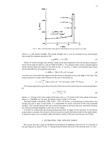
Fig. 11. Plot of ultimate shear stress against radial distance from the centre of the shaft
where o.Is is the tensile strength. The tensile strength can in turn be estimated from the hardness
data using the empirical expression [4]
cTS(MPa) = 3.2 x HV. (5)
Values of tensile strength and ultimate shear stress were estimated from the hardness measure-
ments using Eqns (4) and (5), and are listed in Table 2. The ultimate shear stress is plotted against
radial distance from the centre of the shaft in Fig. 11. As Fig. 1 1 shows, the ultimate shear stress
can be described by the empirical expression
k, (MPa) = 700+8.78 x 10⁻³(r/mm)3 (6)
over the core of the shaft (the region from the centre of the shaft to the inner edge of the case). The
torque required to cause shear fracture of the core is then given by
23.5mm
r = 27c (700+8.78x 10⁻³r')r2drNmm=2.06x 10⁷Nmm. (7)
0
The torque required to cause shear fracture of the case can be found from the standard expression
[41
2zk,(r: - r:)
r= (8)
3 '
where Y, (= 25 mm) is the outer radius of the case, and rz (= 23.5 mm) is the inner radius of the case.
Since k, x 1760 MPa for the case, the failure torque is 0.98 x lo7 N mm.
The total torque is therefore (2.06+0.98)= 3.04 x 10⁷Nmm. It is interesting to notice that, even
though the case is only 1.5mm thick, it is responsible for nearly one-third of the total torsional
strength. This is partly because the case is more than twice as strong as the core, and partly because
the torsional strength depends on the cube of the radius.
It should be stressed that the present analysis provides an upper-bound estimate for the failure
torque since it assumes that all parts of the cross-section reach the failure strain at the same instant.
In practical terms, this is unlikely unless the failure strains of the core and the case are similar.
4. ESTIMATING THE APPLIED FORCE
We assume that the torque on the shaft was produced by applying a lateral force F to the end of
the steering arm as shown in Fig. 2. Taking moments about the axis of the steering shaft, we have