
Page 25 - Failure Analysis Case Studies II
P. 25
12
I
.-c
F
I
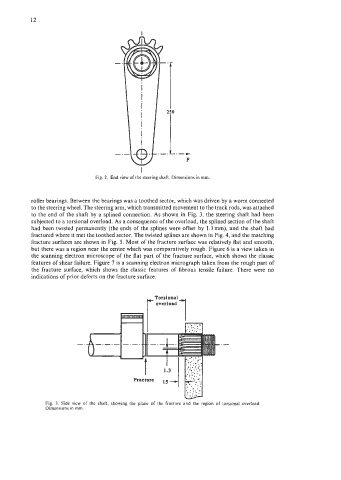
Fig. 2. End view of the steering shaft. Dimensions in mm.
roller bearings. Between the bearings was a toothed sector, which was driven by a worm connected
to the steering wheel. The steering arm, which transmitted movement to the track rods, was attached
to the end of the shaft by a splined connection. As shown in Fig. 3, the steering shaft had been
subjected to a torsional overload. As a consequence of the overload, the splined section of the shaft
had been twisted permanently (the ends of the splines were offset by 1.3mm), and the shaft had
fractured where it met the toothed sector. The twisted splines are shown in Fig. 4, and the matching
fracture surfaces are shown in Fig. 5. Most of the fracture surface was relatively flat and smooth,
but there was a region near the centre which was comparatively rough. Figure 6 is a view taken in
the scanning electron microscope of the flat part of the fracture surface, which shows the classic
features of shear failure. Figure 7 is a scanning electron micrograph taken from the rough part of
the fracture surface, which shows the classic features of fibrous tensile failure. There were no
indications of prior defects on the fracture surface.
171
..._ .
t
..-
' : I
Fracture
Fig. 3. Side view of the shaft, showing the plane of the fracture and the region of torsional overload.
Dimensions in mm.