
Page 21 - Failure Analysis Case Studies II
P. 21
8
F, = x 2.4 x 25.4 x 2 = 23.3 kN. (4)
3.3. Assessment of the theoretical bursting pressure
In the test, the lower bound for the strength of the bolted joint was measured as FFractuIe = 22 kN.
This also corresponds to the mean value of the forces calculated from Eqns (3) and (4).
From the spacing of the bolts (108 mm), one obtains the force at fracture per unit length:
22 x 103
T=-- - 204Nmm-’.
108
The burst pressure can be calculated from this, using the diameter of the silo (6m), as
2 x 204
- 0.068 Nmm-’.
Pburst = __ -
6000
The corresponding level over the ruptured ring is
This is equivalent to the height of 4.7 rings of the silo, and would mean that the level of the slurry
was approximately in the middle of the third ring (counted from the top).
3.4. Spurting distance
From the visual inspection at the site of the accident, the approximate spurting distance of the
slurry of 30m is known. Since this was not a simple parabolical throw, but the jet was dispersed
further after hitting the ground, the process can only be calculated approximately. The intention of
such an assessment is, of course, to determine the filling height of the silo.
The horizontal velocity of the jet is given by u= qSH, and from the distance the jet travelled
one obtains
9
= Dd2(HL - Ah) ’
Thus, the height of the liquid above the leak is
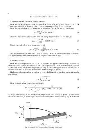
d* = S/D is the portion of the distance that the jet travels after hitting the ground, cp is the factor
of constriction of the jet (normally cp I I), and the other symbols are explained by Fig. 8. If different
D
~~- ~ ~ ___ _ _ _ ~
-30 m
Fig 8 Schematic view of the spurting of the slurry from the silo