
Page 17 - Failure Analysis Case Studies II
P. 17
4
Fig. 1. Damaged silos: view of the site.
, (,, , ,
k l i - I ,./ , i ,
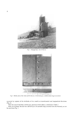
Fig 2. Bolted joints of the sheets used for the silo In the lower part, a reinforcement nng was attached
occurred by rupture of the boltholes of the vessel in circumferential and longitudinal directions
(Fig. 4).
After the search had been carried out, specimens were taken, as detailed in Table 1.
After the accident, the silo was still full up to the seventh ring (counted from the bottom), as can
be seen from Fig. 5.