
Page 26 - Failure Analysis Case Studies II
P. 26
13
i
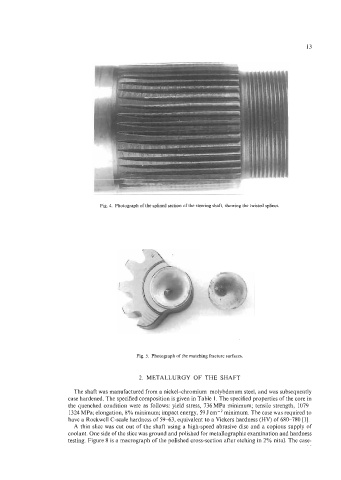
Fig. 4. Photograph of the splined section of the steering shaft, showing the twisted splines.
Fig. 5. Photograph of the matching fracture surfaces.
2. METALLURGY OF THE SHAFT
The shaft was manufactured from a nickel-chromium-molybdenum steel, and was subsequently
case hardened. The specified composition is given in Table 1. The specified properties of the core in
the quenched condition were as follows: yield stress, 736 MPa minimum; tensile strength, 1079-
1324 MPa; elongation, 8% minimum; impact energy, 59 J cm-’ minimum. The case was required to
have a Rockwell C-scale hardness of 59-63, equivalent to a Vickers hardness (HV) of 680-780 [l].
A thin slice was cut out of the shaft using a high-speed abrasive disc and a copious supply of
coolant. One side of the slice was ground and polished for metallographic examination and hardness
testing. Figure 8 is a macrograph of the polished cross-section after etching in 2% nital. The case-