
Page 79 - Failure Analysis Case Studies II
P. 79
64
6’
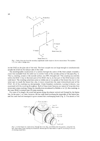
X branch
Y branch
Steam chest (Y)
Fig. 1. Path of the pipe from the secondary superheater outlet header to the two steam chests. The numbers
1,2, 3 etc. refer to hanger sites.
on the HAZ on the pipe side of the weld. The boat sample was not large enough to simultaneously
sample the HAZ on the reducer side of this weld.
The metallographic examination of a section through the centre of the boat sample revealed a
crack that extended from the weld root to within 2mm of the outside surface of the pipe (Fig. 3).
That is, cracking, unseen at the outside surface, was 90% through-wall. This cracking was entirely
within the HAZ. It lay in the inner part of the HAZ, that is, in that part of the HAZ closest to the
weld metal. The cracking sometimes came to within one or two grains of the fusion line, but it was
never seen to touch the fusion line: also, it never strayed into the outer (intercritical) part of the
HAZ. All of the cracking was intergranular. Grain boundary cavitation, varying in density, was
associated with the cracking throughout. Both of these latter features are typical of long-time (low
strain rate) creep cracking. Using the classification introduced by Schiiler et al. [l], this cracking, in
the inner HAZ, is termed type 111 creep cracking.
For most of its length, the crack had grown along the almost vertical wall formed by the fusion
line. In the outer 1 or 2mm, however, the last weld bead overhung the remainder of the fusion line,
and the crack had not managed to grow around that overhanging bead (Fig. 3). The density of the
Eight
Fig. 2. At the forged tee, steam enters through the 12 in. line, and divides into two streams, along the 8 in.
lines. Sites where creep cracking was found are labelled type 111, base metal, or type IV, according to the sort
of cracking found there.