
Page 82 - Failure Analysis Case Studies II
P. 82
67
probably a type I [l] creep crack. However, no other cracking, and very little deterioration, was
seen in the 12 in. line.
Examination of the tee forging by MT and in situ metallography revealed what appeared to be
creep cracking in the forging at two separate sites. (These cracks were open to the surface, rather
than buried.) The decision was made to remove and replace the tee and its reducers.
4. EXAMINATIONS OF THE SCRAPPED TEE, AND OF THE REDUCERS AND
THEIR WELDS
When the retired tee became available, parts of it were examined by conventional, as opposed to
replica, or boat sample, metallographic examination. The reducer side HAZ of the reducer-to-pipe
weld on the X side of the tee was one site that was examined. (The major cracking that started this
investigation had been in the pipe HAZ of this same weld.) There were cracks at three different
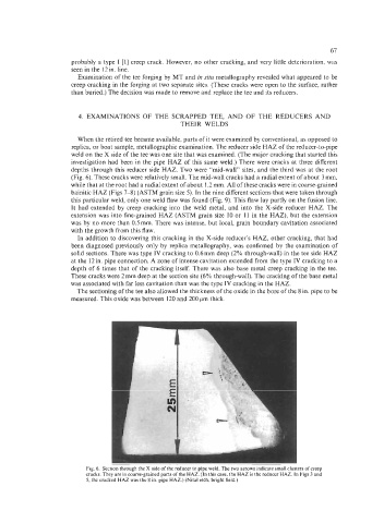
depths through this reducer side HAZ. Two were “mid-wall” sites, and the third was at the root
(Fig. 6). These cracks were relatively small. The mid-wall cracks had a radial extent of about 3 mm,
while that at the root had a radial extent of about 1.2 mm. All of these cracks were in coarse-grained
bainitic HAZ (Figs 7-8) (ASTM grain size 5). In the nine different sections that were taken through
this particular weld, only one weld flaw was found (Fig. 9). This flaw lay partly on the fusion line.
It had extended by creep cracking into the weld metal, and into the X-side reducer HAZ. The
extension was into fine-grained HAZ (ASTM grain size 10 or 11 in the HAZ), but the extension
was by no more than 0.5 mm. There was intense, but local, grain boundary cavitation associated
with the growth from this flaw.
In addition to discovering this cracking in the X-side reducer’s HAZ, other cracking, that had
been diagnosed previously only by replica metallography, was confirmed by the examination of
solid sections. There was type IV cracking to 0.6mm deep (2% through-wall) in the tee side HAZ
at the 12 in. pipe connection. A zone of intense cavitation extended from the type IV cracking to a
depth of 6 times that of the cracking itself. There was also base metal creep cracking in the tee.
These cracks were 2mm deep at the section site (6% through-wall). The cracking of the base metal
was associated with far less cavitation than was the type IV cracking in the HAZ.
The sectioning of the tee also allowed the thickness of the oxide in the bore of the 8 in. pipe to be
measured. This oxide was between 120 and 200pm thick.
Fig. 6. Section through the X side of the reducer to pipe weld The two arrows indicate small clusters of creep
cracks. They are in coarse-grained parts of the HAZ (In this case, the HAZ is the reducer HAZ In Figs 3 and
5, the cracked HAZ was the 8 in pipe HA2 ) (Nital etch, bright field.)