
Page 81 - Failure Analysis Case Studies II
P. 81
66
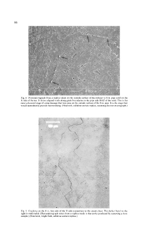
Fig. 4. Photomicrograph from a replica taken on the outside surface of the reducer to 8 in. pipe weld on the
X side of the tee. It shows aligned voids along grain boundaries in the pipe side HAZ of the weld. This is the
most advanced stage of creep damage that was seen on the outside surface of the 8 in. pipe. It is the stage that
would immediately precede microcrcking. (Nital etch, cellulose acetate replica, scanning electron micrograph.)
Fig. 5. Cracking on the 8 in. line side of the Y-side connection to the steam chest. The darker band to the
right is weld metal. (Photomicrograph taken from a replica made in the cavity produced by removing a boat
sample.) (Nital etch, bright field, cellulose acetate replica.)