
Page 98 - Failure Analysis Case Studies II
P. 98
83
P
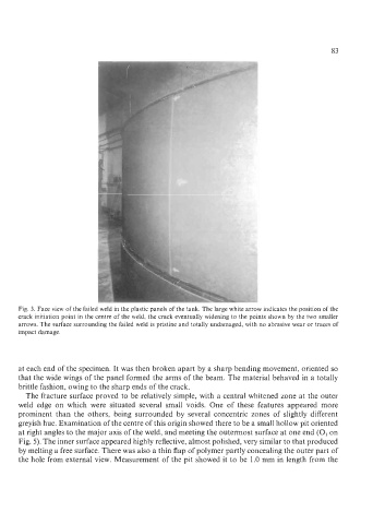
Fig. 3. Face view of the failed weld in the plastic panels of the tank. The large white arrow indicates the position of the
crack initiation point in the centre of the weld, the crack eventually widening to the points shown by the two smaller
arrows. The surface surrounding the failed weld is pristine and totally undamaged, with no abrasive wear or traces of
impact damage.
at each end of the specimen. It was then broken apart by a sharp bending movement, oriented so
that the wide wings of the panel formed the arms of the beam. The material behaved in a totally
brittle fashion, owing to the sharp ends of the crack.
The fracture surface proved to be relatively simple, with a central whitened zone at the outer
weld edge on which were situated several small voids. One of these features appeared more
prominent than the others, being surrounded by several concentric zones of slightly different
greyish hue. Examination of the centre of this origin showed there to be a small hollow pit oriented
at right angles to the major axis of the weld, and meeting the outermost surface at one end (0, on
Fig. 5). The inner surface appeared highly reflective, almost polished, very similar to that produced
by melting a free surface. There was also a thin flap of polymer partly concealing the outer part of
the hole from external view. Measurement of the pit showed it to be 1.0 mm in length from the