
Page 103 - Failure Analysis Case Studies II
P. 103
88
The appearance of sub-critical cracks on the outer surface of an intact weld confirmed the
picture which had emerged from the study of the fracture surface, namely that cracks had been
initiated at pre-existing defects in the welds (small pits at the outer surface), and had grown slowly
as a result of superimposed pressure from the full tank. As the tank was emptied, the pressure fell,
and slow crack growth stopped. With time, as the cracks grew in size, the stress concentration at
their ends became more severe, and when crack growth resumed on refilling the tank, the speed of
crack growth increased. This would account for the increasing area under each of the zones shown
in Fig. 5. Sub-critical cracks were found elsewhere on the main fracture surface (Fig. 6), and
represent cracks which had grown but not propagated catastrophically. It remained to investigate
what extra information could be gleaned from closer examination of the welds themselves, particu-
larly comparison of welds which showed no cracks whatsoever (despite being exposed to similar
pressures to those which failed) and the intact welds.
5. Mechanical testing of welds and panels
An initial test made on large lengths of panel material cut across the welds had indicated that
the fracture surface of the intact weld possessed fewer defects in the weld than that from the critical
weld. The samples were simply cut using a circular saw, and bent over with the textured, external
surface subjected to the greatest tensile stress, to cause failure in the weakest part. In both cases,
one bend was insufficient to break the samples. Both samples broke essentially in the same way,
by brittle fracture along the centreline of the weld. The resultant fracture surfaces were very
different, however, with a greater density of visible defects from the failed weld. Tensile tests on
two dumbbells from each of the two types of weld was conducted to confirm the hypothesis.
5.1. Etching of weld zones
It was of interest to see if the weld zone could be revealed by an appropriate etching method
applied to the cross-section produced by polishing. Several reagents were evaluated on a separate
sample, including hot chromic acid of various strengths, nitric acid and, finally, organic fluids
known to swell or partially dissolve polypropylene. When xylene was used as a polishing medium
for the final stage of the polishing process, it was found to show the weld zone very clearly. The
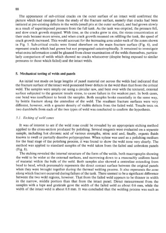
method was applied to standard samples of the weld taken from the failed and unbroken panels
(Fig. 8).
The etching revealed the internal structure of the form of the welds, both macrographs showing
the weld to be wider at the external surfaces, and narrowing down to a reasonably uniform band
of material within the bulk of the weld. Both samples also showed a centreline extending from
bead to bead, which presumably represents the direct contact surface between the original panels
when they were brought together during the thermal welding process. It also represents the zone
along which fracture occurred during failure of the tank. There seemed to be a significant difference
between the two weld regions, however. That from the failed weld appears to be thinner in width
in the narrow, middle portion than that from the intact panel. Direct measurement from the
samples with a lupe and graticule gave the width of the failed weld as about 0.6 mm, while the
width of the intact weld is about 0.8 mm. It was concluded that the welding process was such as