
Page 99 - Failure Analysis Case Studies II
P. 99
84
I
TOP
BUlTiESS
UPPER
SINGLE
PANEL
FACTORY FLOOR
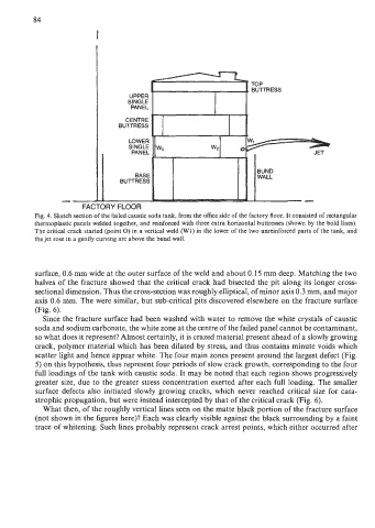
Fig. 4. Sketch section of the failed caustic soda tank, from the office side of the factory floor. It consisted of rectangular
thermoplastic panels welded together, and reinforced with three extra horizontal buttresses (shown by the bold lines).
The critical crack started (point 0) in a vertical weld (W1) in the lower of the two unreinforced parts of the tank, and
the jet rose in a gently curving arc above the bund wall.
surface, 0.6 mm wide at the outer surface of the weld and about 0.15 mm deep. Matching the two
halves of the fracture showed that the critical crack had bisected the pit along its longer cross-
sectional dimension. Thus the cross-section was roughly elliptical, of minor axis 0.3 mm, and major
axis 0.6 mm. The were similar, but sub-critical pits discovered elsewhere on the fracture surface
(Fig. 6).
Since the fracture surface had been washed with water to remove the white crystals of caustic
soda and sodium carbonate, the white zone at the centre of the failed panel cannot be contaminant,
so what does it represent? Almost certainly, it is crazed material present ahead of a slowly growing
crack, polymer material which has been dilated by stress, and thus contains minute voids which
scatter light and hence appear white. The four main zones present around the largest defect (Fig.
5) on this hypothesis, thus represent four periods of slow crack growth, corresponding to the four
full loadings of the tank with caustic soda. It may be noted that each region shows progressively
greater size, due to the greater stress concentration exerted after each full loading. The smaller
surface defects also initiated slowly growing cracks, which never reached critical size for cata-
strophic propagation, but were instead intercepted by that of the critical crack (Fig. 6).
What then, of the roughly vertical lines seen on the matte black portion of the fracture surface
(not shown in the figures here)? Each was clearly visible against the black surrounding by a faint
trace of whitening. Such lines probably represent crack arrest points, which either occurred after