
Page 100 - Failure Analysis Case Studies II
P. 100
85
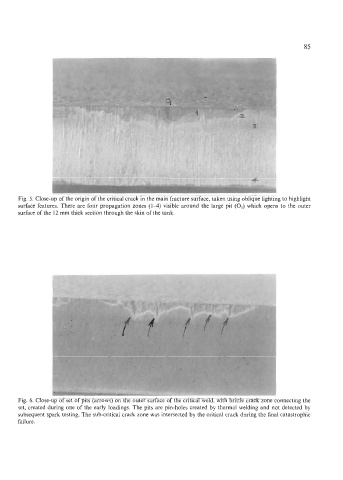
Fig. 5. Close-up of the origin of the critical crack in the main fracture surface, taken using oblique lighting to highlight
surface features. There are four propagation zones (14) visible around the large pit (0,) which opens to the outer
surface of the 12 mm thick section through the skin of the tank.
Fig. 6. Close-up of set of pits (arrows) on the outer surface of the critical weld, with brittle crack zone connecting the
set, created during one of the early loadings. The pits are pin-holes created by thermal welding and not detected by
subsequent spark testing. The sub-critical crack zone was intersected by the critical crack during the final catastrophic
failure.