
Page 105 - Failure Analysis Case Studies II
P. 105
90
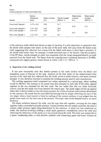
Table 1
Tensile properties of welds from failed tank
Section Mean strain Mean tensile
dimensions Strain at break Tensile strength at break strength
Sample (mm) (%I (MN m-*) (%) (MN m-*)
Good weld, Sample 1 11.75 x 10.2 0.28 21.7
0.30 21.3
Good weld, Sample 2 1 1.8 x 10.4 0.32 20.8
Poor weld, Sample 1 11.6x9.8 0.20 20.7
0.21 20.4
Poor weld, Sample 2 11.6~ 10.5 0.21 20.1
of the alternate welds which had shown no sign of cracking. It is also important to appreciate that
the whole weld samples were taken, in the case of the poor weld, well away from the failure zone
itself, suggesting that whatever was wrong with the failed weld seems to have been a property of
the whole weld rather than, for example, a small restricted zone of the feature. One key property
of the PP sheet, tensile strength at yield, was consistent with the values measured directly on weld
material from the failed tank. The figure from the manufacturer’s technical literature is 20 MPa,
compared with slightly greater values shown in Table 1 (20.1-2 1.7 MN m-’).
6. Inspection of the welding method
It was now reasonably clear that defects present in the outer surface were the direct and
immediate cause of fracture of the tank. Analysis of the four welds on the unbuttressed lower
portion of the tank had also indicated that the welds varied in defect density, and hence intrinsic
strength. It was therefore relevant to examine the welding process used in tank manufacture.
The welding apparatus itself comprised two tables separated by a central gap, where welding
would be effected. The surfaces to be joined were first clamped on each side of the table, aligned
together in the way intended for the butt weld. The two tables then slid out under hydraulic
control, and the hot blade rose from beneath the central gap. The panel edges moved up against
either side of the hot blade to start the fusion process, for a time of contact and pressure determined
by the operator. He stated that he controlled the heating time by simply observing the state of the
two edges: when a bead started to form by melting of the contact surfaces, it was judged that the
panels were ready for the next step in the process. The exact time would depend mainly on panel
thickness.
The blade withdrew beneath the table, and the tops then slid together, carrying the hot edges
together under controlled hydraulic pressure. Fusion between the two panels occurred, the time of
contact under pressure again being determined by the operator. A spark test was conducted on
welds, the method involving holding a small spark generator immediately above the weld and
observing the behaviour of the spark as it was moved along the weld. The joint was supported on
a metal, conducting table, so that should a pinhole void connecting upper and lower surfaces be