
Page 107 - Failure Analysis Case Studies II
P. 107
92
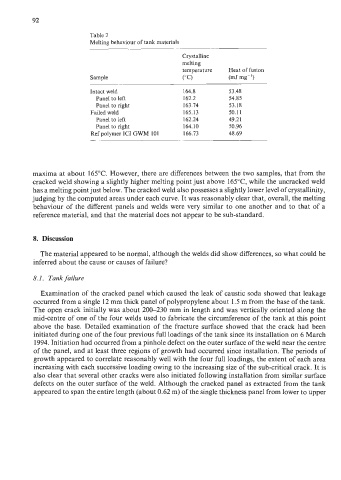
Table 2
Melting behaviour of tank materials
Crystalline
melting
temperature Heat of fusion
Sample ("C) (mJ mg-')
Intact weld 164.8 53.48
Panel to left 162.2 54.85
Panel to right 163.74 53.18
Failed weld 165.13 50.11
Panel to left 162.24 49.21
Panel to right 164.10 50.96
Ref polymer IC1 GWM 101 166.73 48.69
maxima at about 165°C. However, there are differences between the two samples, that from the
cracked weld showing a slightly higher melting point just above 165"C, while the uncracked weld
has a melting point just below. The cracked weld also possesses a slightly lower level of crystallinity,
judging by the computed areas under each curve. It was reasonably clear that, overall, the melting
behaviour of the different panels and welds were very similar to one another and to that of a
reference material, and that the material does not appear to be sub-standard.
8. Discussion
The material appeared to be normal, although the welds did show differences, so what could be
inferred about the cause or causes of failure?
8.1. Tank failure
Examination of the cracked panel which caused the leak of caustic soda showed that leakage
occurred from a single 12 mm thick panel of polypropylene about 1.5 m from the base of the tank.
The open crack initially was about 200-230 mm in length and was vertically oriented along the
mid-centre of one of the four welds used to fabricate the circumference of the tank at this point
above the base. Detailed examination of the fracture surface showed that the crack had been
initiated during one of the four previous full loadings of the tank since its installation on 6 March
1994. Initiation had occurred from a pinhole defect on the outer surface of the weld near the centre
of the panel, and at least three regions of growth had occurred since installation. The periods of
growth appeared to correlate reasonably well with the four full loadings, the extent of each area
increasing with each successive loading owing to the increasing size of the sub-critical crack. It is
also clear that several other cracks were also initiated following installation from similar surface
defects on the outer surface of the weld. Although the cracked panel as extracted from the tank
appeared to span the entire length (about 0.62 m) of the single thickness panel from lower to upper