
Page 110 - Failure Analysis Case Studies II
P. 110
95
s [: T
. I a
I A
r. ,
v
DAM
DESIGN BARREL
DESIGN
-
c
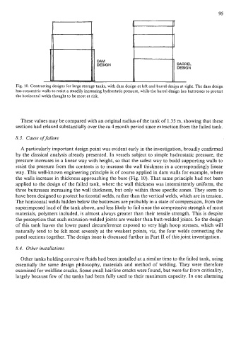
Fig. 10. Contrasting designs for large storage tanks, with dam design at left and barrel design at right. The dam design
has concentric walls to resist a steadily increasing hydrostatic pressure, while the barrel design has buttresses to protect
the horizontal welds thought to be most at risk.
These values may be compared with an original radius of the tank of 1.35 m, showing that these
sections had relaxed substantially over the ca 4 month period since extraction from the failed tank.
8.3. Cause of failure
A particularly important design point was evident early in the investigation, broadly confirmed
by the classical analysis already presented. In vessels subject to simple hydrostatic pressure, the
pressure increases in a linear way with height, so that the safest way to build supporting walls to
resist the pressure from the contents is to increase the wall thickness in a correspondingly linear
way. This well-known engineering principle is of course applied in dam walls for example, where
the walls increase in thickness approaching the base (Fig. 10). That same principle had not been
applied to the design of the failed tank, where the wall thickness was intermittently uniform, the
three buttresses increasing the wall thickness, but only within three specific zones. They seem to
have been designed to protect horizontal welds, rather than the vertical welds, which are in tension.
The horizontal welds hidden below the buttresses are probably in a state of compression, from the
superimposed load of the tank above, and less likely to fail since the compressive strength of most
materials, polymers included, is almost always greater than their tensile strength. This is despite
the perception that such extrusion-welded joints are weaker than butt-welded joints. So the design
of this tank leaves the lower panel circumference exposed to very high hoop stresses, which will
naturally tend to be felt most severely at the weakest points, viz, the four welds connecting the
panel sections together. The design issue is discussed further in Part I1 of this joint investigation.
8.4. Other installations
Other tanks holding corrosive fluids had been installed at a similar time to the failed tank, using
essentially the same design philosophy, materials and method of welding. They were therefore
examined for weldline cracks. Some small hairline cracks were found, but were far from criticality,
largely because few of the tanks had been fully used to their maximum capacity. In one alarming