
Page 114 - Failure Analysis Case Studies II
P. 114
99
I 300 c
24
22
24
12
24
k-0 2700-4
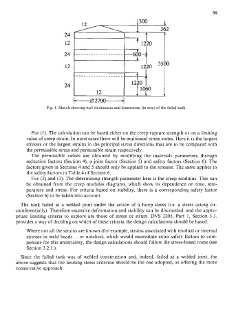
Fig. 1. Sketch showing wall thicknesses and dimensions (in mm) of the failed tank.
For (1). The calculation can be based either on the creep rupture strength or on a limiting
value of creep strain. In most cases there will be multiaxial stress states. Here it is the largest
stresses or the largest strains in the principal stress directions that are to be compared with
the permissible stress and permissible strain respectively.
The permissible values are obtained by modifying the materials parameters through
reduction factors (Section 4), a joint factor (Section 5) and safety factors (Section 6). The
factors given in Sections 4 and 5 should only be applied to the stresses. The same applies to
the safety factors in Table 4 of Section 6.
For (2) and (3). The determining strength parameter here is the creep modulus. This can
be obtained from the creep modulus diagrams, which show its dependence on time, tem-
perature and stress. For criteria based on stability, there is a corresponding safety factor
(Section 6) to be taken into account.
The tank failed at a welded joint under the action of a hoop stress (Le. a stress acting cir-
cumferentially). Therefore excessive deformation and stability can be discounted, and the appro-
priate limiting criteria to explore are those of stress or strain. DVS 2205, Part 1, Section 3.3.
provides a way of deciding on which of these criteria the design calculations should be based.
Where not all the strains are known (for example, strains associated with residual or internal
stresses in weld beads.. . or notches), which would necessitate extra safety factors to com-
pensate for this uncertainty, the design calculations should follow the stress-based route (see
Section 3.2.1 .).
Since the failed tank was of welded construction and, indeed, failed at a welded joint, the
above suggests that the limiting stress criterion should be the one adopted, as offering the more
conservative approach.