
Page 118 - Failure Analysis Case Studies II
P. 118
103
E3
--.
0 1 2 3
DVS 2205 thickness
failed tank thickness
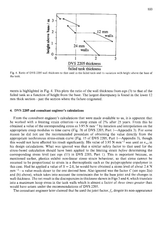
Fig. 4. Ratio of DVS 2205 wall thickness to that used in the failed tank and its variation with height above the base of
the tank.
ments is highlighted in Fig. 4. This plots the ratio of the wall thickness from eqn (3) to that of the
failed tank as a function of height from the base. The largest discrepancy is found in the lower 12
mm thick section-just the section where the failure originated.
4. DVS 2205 and consultant engineer's calculations
From the consultant engineer's calculations that were made available to us, it is apparent that
he worked with a limiting strain criterion-a creep strain of 2% after 25 years. From this he
obtained a value of the corresponding stress as 3.95 N mm-2 by iteration and interpolation on the
appropriate creep modulus vs time curve (Fig. 26 of DVS 2205, Part 1-Appendix 3). For some
reason he did not use the recommended procedure of obtaining the value directly from the
appropriate isochronous stress-strain curve (Fig. 15 of DVS 2205, Part I-Appendix 3), though
this would not have affected his result significantly. His value of 3.95 N mm-2 was used as ozul in
his design calculations. What was ignored was that a similar safety factor to that used for the
stress-based calculation should have been applied to the limiting strain before determining the
corresponding stress level (see eqn (11) in DVS 2205, Part 1). This is important because, as
mentioned earlier, plastics exhibit non-linear stress-strain behaviour, so that stress cannot be
assumed to be proportional to strain in a thermoplastic such as the polypropylene copolymer in
this case. Had he applied a value of S = 2.0, he would have obtained a stress level of about 2.4 N
mm-2-a value much closer to the one derived here. Also ignored was the factor C (see eqns 2(a)
and (b) above), which takes into account the constraints due to the base joint and the changes in
wall thickness. The net result is the discrepancies in thickness shown in Figs 3 and 4, which translate
into a maximum hoop stress in the tank walls which is almost a factor of three times greater than
would have arisen under the recommendations of DVS 2205.
The consultant engineer later claimed that he used the joint factor,&, despite its non-appearance