
Page 120 - Failure Analysis Case Studies II
P. 120
105
n
c;‘
E
-2 -1 0 i 2
log (t / years)
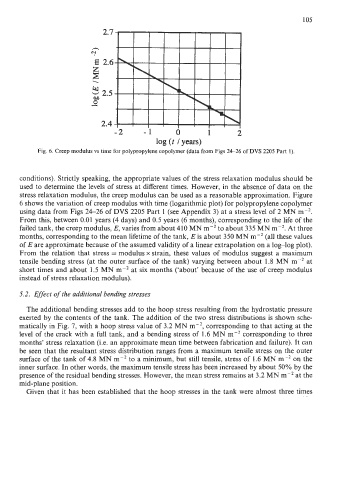
Fig. 6. Creep modulus vs time for polypropylene copolymer (data from Figs 24-26 of DVS 2205 Part 1).
conditions). Strictly speaking, the appropriate values of the stress relaxation modulus should be
used to determine the levels of stress at different times. However, in the absence of data on the
stress relaxation modulus, the creep modulus can be used as a reasonable approximation. Figure
6 shows the variation of creep modulus with time (logarithmic plot) for polypropylene copolymer
using data from Figs 24-26 of DVS 2205 Part 1 (see Appendix 3) at a stress level of 2 MN m-*.
From this, between 0.01 years (4 days) and 0.5 years (6 months), corresponding to the life of the
failed tank, the creep modulus, E, varies from about 410 MN m-’ to about 335 MN m-’. At three
months, corresponding to the mean lifetime of the tank, E is about 350 MN m-2 (all these values
of E are approximate because of the assumed validity of a linear extrapolation on a log-log plot).
From the relation that stress = modulus x strain, these values of modulus suggest a maximum
tensile bending stress (at the outer surface of the tank) varying between about 1.8 MN m-* at
short times and about 1.5 MN m-2 at six months (‘about’ because of the use of creep modulus
instead of stress relaxation modulus).
5.2. Effect of the additional bending stresses
The additional bending stresses add to the hoop stress resulting from the hydrostatic pressure
exerted by the contents of the tank. The addition of the two stress distributions is shown sche-
matically in Fig. 7, with a hoop stress value of 3.2 MN m-2, corresponding to that acting at the
level of the crack with a full tank, and a bending stress of 1.6 MN mV2 corresponding to three
months’ stress relaxation (Le. an approximate mean time between fabrication and failure). It can
be seen that the resultant stress distribution ranges from a maximum tensile stress on the outer
surface of the tank of 4.8 MN mU2 to a minimum, but still tensile, stress of 1.6 MN m-2 on the
inner surface. In other words, the maximum tensile stress has been increased by about 50% by the
presence of the residual bending stresses. However, the mean stress remains at 3.2 MN m-’ at the
mid-plane position.
Given that it has been established that the hoop stresses in the tank were almost three times