
Page 116 - Failure Analysis Case Studies II
P. 116
101
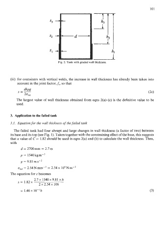
Fig. 2. Tank with graded wall thickness.
(iii) for containers with vertical welds, the increase in wall thickness has already been taken into
account in the joint factor,f,, so that
The largest value of wall thickness obtained from eqns 2(a)-(c) is the definitive value to be
used.
3. Application to the failed tank
3.1, Equation for the wall thickness of the failed tank
The failed tank had four abrupt and large changes in wall thickness (a factor of two) between
its base and its top (see Fig. 1). Taken together with the constraining effect of the base, this suggests
that a value of C = 1.82 should be used in eqns 2(a) and (b) to calculate the wall thickness. Then,
with
d = 2700mm = 2.7m
p = 1540 kgm-3
g = 9.81 m s-2
ozul = 2.54Nmm-’ = 2.54~ 106Nm-*
The equation for s becomes
2.7 x 1540 x 9.81 x h
S= 1.82~
2 x 2.54 x 106
= 1.46~ 10-2h (3)