
Page 119 - Failure Analysis Case Studies II
P. 119
104
in his original calculations, and its non-applicability to a calculation based on a limiting strain.
Even then, he took a value of,fs of 0.8, corresponding to that for heated-tool, butt-welding in DVS
2205. The design code is quite clear that where hot-gas, extrusion is used, as it was for the horizontal
welds in the failed tank, the lower value offs = 0.6 should have been used.
5. Extra bending strains
In Part I of this work, it was noted that extra strains were introduced in one of the stages of
fabricating the tank. The tank was built up of rectangular, flat, polypropylene panels, the edge of
which were butt welded together in a machine to produce a flat strip whose length equalled the
circumference of the tank. This strip was then bent round into a circular hoop and its ends welded
together to form a section of the tank. The bending was done mechanically with no assistance from
elevated temperatures such as would have been used in thermoforming, and with no subsequent
annealing. Thus the strains associated with the bending were permanent and contributed to the
overall strain in the tank walls.
5.1. Determining the extra strains and resulting stresses
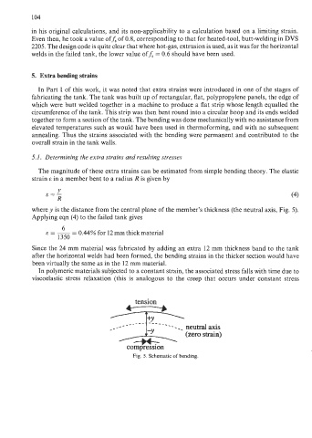
The magnitude of these extra strains can be estimated from simple bending theory. The elastic
strain E in a member bent to a radius R is given by
Y
E=- (4)
R
where y is the distance from the central plane of the member’s thickness (the neutral axis, Fig. 5).
Applying eqn (4) to the failed tank gives
6
E=-- - 0.44% for 12 mm thick material
1350
Since the 24 mm material was fabricated by adding an extra 12 mm thickness band to the tank
after the horizontal welds had been formed, the bending strains in the thicker section would have
been virtually the same as in the 12 mm material.
In polymeric materials subjected to a constant strain, the associated stress falls with time due to
viscoelastic stress relaxation (this is analogous to the creep that occurs under constant stress
tension
------.I neutral axis
(zero strain)
compression
Fig. 5. Schematic of bending.