
Page 122 - Failure Analysis Case Studies II
P. 122
I07
significant factor in causing the failure. The fact that one, or perhaps two, of the vertical welds, in
particular, were of poorer quality than the others (see Part 1) would have been accommodated by
the reduction and safety factors enshrined in the code. Reinforcing the horizontal welds in the
tank walls, but not the vertical ones, reflects a basic lack of comprehension of the stresses involved.
The largest stresses are those acting horizontally (i.e. circumferentially) and are tensile, whilst the
vertical stresses are much smaller and, in the absence of local deformation, are more likely to be
compressive. Finally, the stage of manufacture that involved inducing permanent bending strains
into the tank walls made what was already a high risk of failure even higher by adding up to 50%
to the maximum stress arising from the hydrostatic pressure exerted by the tank's contents. Taken
together, these factors made the premature failure of the tank inevitable.
Acknowledgements
The authors would like to thank the insurers, Independent Insurance Ltd and loss adjusters,
Gillies Adjusting Ltd, for permission to publish the results of this investigation, and the DVS-
Verlag GmbH for permission to reproduce Figs 7, 15 and 24-26 of DVS 2205 Part 1.
Appendix 1
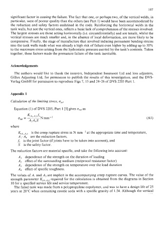
Calculation of the limiting stress, gZul
as
Equation (1) of DVS 2205, Part 1 [5] gives CT,,~
where
is the creep rupture stress in N mmP2 at the appropriate time and temperature,
A ,-A4 are the reduction factors,
is the joint factor (if joints have to be taken into account), and
S is the safety factor.
The reduction factors are material-specific, and take the following into account:
A, dependence of the strength on the duration of loading
A2 effect of the surrounding medium (reciprocal resistance factor)
A3 dependence of the strength on temperature over the load duration
A4 effect of specific toughness.
The values of A, and A3 are implicit in the accompanying creep rupture curves. The value of the
strength parameter required for the calculation is obtained from the diagrams in Section
10 for a specified service life and service temperature.
The failed tank was made from a polypropylene copolymer, and was to have a design life of 25
years at 20°C when containing caustic soda with a specific gravity of 1.54. Although the vertical