
Page 117 - Failure Analysis Case Studies II
P. 117
102
If h is expressed in mm, eqn (3) gives s also in mm. This eqn allows the minimum wall thickness at
any vertical position on the container to be calculated.
The failed tank had a design capacity of 20 m3, so that its fill level, corresponding to the
maximum of the hydrostatic head h,,,, was
volume
hmax =
base area
20x4
-- m
-
red
20x4
= 3.5 mor 3500 mm
Then, from eqn (3), the minimum wall thickness just above the base should have been 51.1 mm.
In fact it was 24 mm-just over a factor of 2 less.
3.2. Comparison between the failed tank and D VS 2205
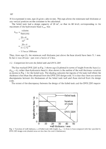
The line marked DVS 2205 in Fig. 3 shows eqn (3) plotted in terms of height from the base (Le.
(h,,, - h), rather than hydrostatic head h. Also shown is the outline of the wall thickness variation
as shown in Fig. 1 for the failed tank. The shading indicates the regions of the tank wall where the
thickness is less than that obtained from the DVS 2205 design code. It is clear that there are serious
discrepancies between the thicknesses of the failed tank wall and those derived from the design
code.
The extent of the discrepancy between the design of the failed tank and the DVS 2205 require-
h'jfailed tank
E3
-
\
8 location
h of crack
'" R"I n <, , ., . . . ;::*
I .
.
I
0 10 20 * . . 30 . 40 50
wall thickness / mm
Fig. 3. Variation of wall thickness, s, of failed tank with height, h,,,-h, from its base compared with that specified by
DVS 2205 design code (shaded areas are less than the code's thicknesses).