
Page 138 - Fair, Geyer, and Okun's Water and wastewater engineering : water supply and wastewater removal
P. 138
JWCL344_ch03_061-117.qxd 8/17/10 7:48 PM Page 100
100 Chapter 3 Water Sources: Groundwater
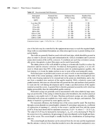
Table 3.5 Recommended Well Diameters
Anticipated Nominal Size Optimum Size Smallest Size
Well Yield of Pump Bowls of Well Casing of Well Casing
(gpm) (in.) (in.) (in.)
Less than 100 4 6ID 5ID
75 to 175 5 8ID 6ID
150 to 400 6 10 ID 8ID
350 to 650 8 12 ID 10 ID
600 to 900 10 14 OD 12 ID
850 to 1,300 12 16 OD 14 OD
1,200 to 1,800 14 20 OD 16 OD
1,600 to 3,000 16 24 OD 20 OD
3
Conversion factors: 1 gpm 5.45 m /d; 1 in. 25.4 mm
size of the hole may be controlled by the equipment necessary to reach the required depth.
Deep wells in consolidated formations are often telescoped in size to permit drilling to re-
quired depths.
The wells are generally lined or cased with mild steel pipe, which should be grouted in
place in order to prevent caving and contamination by vertical circulation and to prevent
undue deterioration of the well by corrosion. If conditions are such that corrosion is unusu-
ally severe, then plastic or glass fiber pipes can be used if practicable.
The intake portion of the well should be as long as economically feasible to reduce the
drawdown and the entrance velocities. In relatively homogeneous aquifers, it is not effi-
cient to obtain more than 90% of the maximum yield. In nonhomogeneous aquifers, the
best strategy is to locate the intake portion in one or more of the most permeable strata.
Perforated pipes or prefabricated screens are used in wells in unconsolidated aquifers.
The width of the screen openings, called the slot size, depends on the critical particle size
of the water-bearing material to be retained and on the grain-size distribution, and is cho-
sen from a standard sieve analysis of the aquifer material. With a relatively coarse and
graded material, slot sizes are selected that will permit the fine and medium-sized particles
to wash into the well during development and to retain a specified portion of the aquifer
material around the screen. A graded filter is thereby generated around the well, which has
higher permeability than the undisturbed aquifer material.
Perforated casings are generally used in uncemented wells when relatively large open-
ings are permissible. If the casing is slotted in place after installation, the smallest practical
opening is one-eighth inch (3.18 mm). Machine-perforated casings are also available.
Fabricated well screens are available in a wide variety of sizes, designs, and materials. The
choice of material is governed by water quality and cost.
For maximum efficiency, the frictional loss of the screen must be small. The head loss
through a screen depends on screen length L, diameter D, percentage open area A p , coefficient
of contraction of openings C c , velocity in the screen v, and the total flow into the screen
3
Q (ft /s). It has been shown that for minimum screen loss, CL>D
6, where C 11.31 C c A P .
The value of CL>D may be increased by increasing C c , A p , or L, or by decreasing D. Thus for
the screen loss to be a minimum, the percentage of open area depends on the length and diam-
eter of the screen. The screen length is usually fixed by the considerations of hydrogeology
and cost.
The screen length and diameter can be selected from the slot size and the requirement
that the entrance velocity be less than that needed to move the unwanted sand particle sizes