
Page 139 - Fair, Geyer, and Okun's Water and wastewater engineering : water supply and wastewater removal
P. 139
JWCL344_ch03_061-117.qxd 8/17/10 7:48 PM Page 101
3.17 Well Construction 101
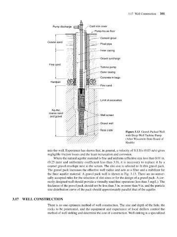
Pump discharge Cast-iron cover
Pump-house floor
Cement grout
Coarse sand
Float pipe
Inner casing
Gravel surcharge
Fine sand
Turbine pump
Outer casing
Concrete in bags
Hardpan
Fine sand
Limit of excavation
Aquifer,
coarse sand
Well screen
and gravel
Gravel wall
Base plate
Figure 3.13 Gravel-Packed Well
with Deep-Well Turbine Pump
(After Wisconsin State Board of
Health)
into the well. Experience has shown that, in general, a velocity of 0.1 ft/s (0.03 m/s) gives
negligible friction losses and the least incrustation and corrosion.
Where the natural aquifer material is fine and uniform (effective size less than 0.01 in.
(0.25 mm) and uniformity coefficient less than 3.0), it is necessary to replace it by a
coarser gravel envelope next to the screen. The slot size is selected to fit this gravel pack.
The gravel pack increases the effective well radius and acts as a filter and a stabilizer for
the finer aquifer material. A gravel pack well is shown in Fig. 3.13. There are no univer-
sally accepted rules for the selection of slot sizes or for the design of a gravel pack. A cor-
rectly designed well should provide a virtually sand-free operation (less than 3 mg/L). The
thickness of the gravel pack should not be less than 3 in. or more than 9 in. and the particle
size distribution curve of the pack should approximately parallel that of the aquifer.
3.17 WELL CONSTRUCTION
There is no one optimum method of well construction. The size and depth of the hole, the
rocks to be penetrated, and the equipment and experience of local drillers control the
method of well sinking and determine the cost of construction. Well sinking is a specialized