
Page 214 - Fair, Geyer, and Okun's Water and wastewater engineering : water supply and wastewater removal
P. 214
JWCL344_ch05_154-193.qxd 8/2/10 9:44 PM Page 176
176 Chapter 5 Water Hydraulics, Transmission, and Appurtenances
Solution:
1. The diameter of the pipes:
3
3
3
At present: Q 13,000 m /d (13,000 m /d) (24 h/d) (60 min/h)(60 s/min) 0.150 m /s
(150 L/s)
S h f >L 100 m/50 km 2‰
3
The nomogram (C 100) of Fig. 5.6 for Q 0.150 m /s and s 2‰ will give a pipe
diameter 500 mm.
Diameter of existing pipe No. 1 500 mm.
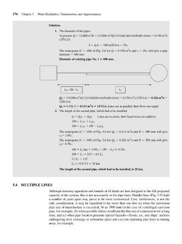
L = 50 − L 1 L 1
2
3
3
3
Q 2 (19,500 m /d) (24 h/d)(60 min/h)(60 s/min) 0.150 m /s (150 L/s) 0.226 m /s
(226 L/s)
3
Q 1 0.226>2 0.113 m /s 113 L/s. Lines are in parallel, their flows are equal.
2. The length of the second pipe, which had to be installed:
h f (h f ) 1 (h f ) 2 Lines are in series, their head losses are additive.
100 L 1 s 1 L 2 s 2
100 L 1 s 1 (50 L 1 )s 2
3
The nomogram (C 100) of Fig. 5.6 for Q 1 0.113 m /s and D 500 mm will give
s 1 1.0‰.
3
The nomogram (C 100) of Fig. 5.6 for Q 2 0.226 m /s and D 500 mm will give
s 2 4.3‰.
100 L 1 km 1.0‰ (50 L 1 ) 4.3‰
100 L 1 215 4.3 L 1
3.3 L 1 115
L 1 115 3.3 35 km
The length of the second pipe, which had to be installed, is 35 km.
5.4 MULTIPLE LINES
Although masonry aqueducts and tunnels of all kinds are best designed to the full projected
capacity of the system, this is not necessarily so for pipe lines. Parallel lines (Fig. 5.9) built
a number of years apart may prove to be more economical. Cost, furthermore, is not the
only consideration. It may be expedient to lay more than one line (a) when the maximum
pipe size of manufacture is exceeded; 36 in. (900 mm) in the case of centrifugal cast-iron
pipe, for example; (b) when possible failure would put the line out of commission for a long
time; and (c) when pipe location presents special hazards—floods, ice, and ships’ anchors
endangering river crossings or submarine pipes and cave-ins rupturing pipe lines in mining
areas, for example.