Page 512 - Fair, Geyer, and Okun's Water and wastewater engineering : water supply and wastewater removal
P. 512

JWCL344_ch13_457-499.qxd  8/7/10  8:49 PM  Page 470


                    470  Chapter 13  Hydraulics of Sewer Systems

                                                                                    C of manhole
                                                                        1
                                                        Energy grade line

                                                                    h   velocity head    h e
                                                                    v 1
                                                 Water surface hydraulic                        2
                                                  grade line slope s 1                  h
                                             v   velocity      h 1  d   depth of flow    8
                                                                    1
                                              1
                                             a   cross-sectional area
                                              1
                                             q   a v   rate of flow
                                              1
                                                  1 1
                                                                                                    h
                                                                                         h           v 2
                                                    Sewer gradient, slope i 1             i
                                                                                                      s 2
                                                                                                    d 2
                                                                                                        h 2  v 2
                                                                                                      i 2
                                                                                                          a 2
                                                                                                          q 2
                                                        Uniform flow             Transition           Uniform flow

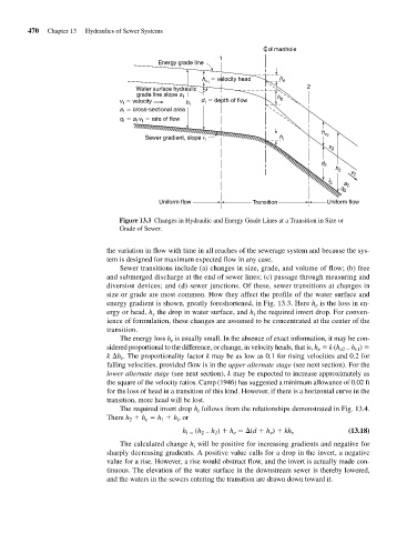
                                             Figure 13.3 Changes in Hydraulic and Energy Grade Lines at a Transition in Size or
                                             Grade of Sewer.


                                         the variation in flow with time in all reaches of the sewerage system and because the sys-
                                         tem is designed for maximum expected flow in any case.
                                             Sewer transitions include (a) changes in size, grade, and volume of flow; (b) free
                                         and submerged discharge at the end of sewer lines; (c) passage through measuring and
                                         diversion devices; and (d) sewer junctions. Of these, sewer transitions at changes in
                                         size or grade are most common. How they affect the profile of the water surface and
                                         energy gradient is shown, greatly foreshortened, in Fig. 13.3. Here h is the loss in en-
                                                                                                   e
                                         ergy or head, h the drop in water surface, and h the required invert drop. For conven-
                                                      s
                                                                                  i
                                          ience of formulation, these changes are assumed to be concentrated at the center of the
                                          transition.
                                             The energy loss h is usually small. In the absence of exact information, it may be con-
                                                           e
                                         sidered proportional to the difference, or change, in velocity heads, that is, h   k (h v2   v1
                                                                                                            h )
                                                                                                   e
                                         k  h . The proportionality factor k may be as low as 0.1 for rising velocities and 0.2 for
                                             v
                                          falling velocities, provided flow is in the upper alternate stage (see next section). For the
                                         lower alternate stage (see next section), k may be expected to increase approximately as
                                         the square of the velocity ratios. Camp (1946) has suggested a minimum allowance of 0.02 ft
                                         for the loss of head in a transition of this kind. However, if there is a horizontal curve in the
                                         transition, more head will be lost.
                                             The required invert drop h follows from the relationships demonstrated in Fig. 13.4.
                                                                  i
                                         There h   h   h   h , or
                                                        1
                                                    e
                                                2
                                                             i
                                                                      h )   h   (d   h )   kh
                                                              h i   (h 2   1  e       v     v               (13.18)
                                             The calculated change h will be positive for increasing gradients and negative for
                                                                 i
                                         sharply decreasing gradients. A positive value calls for a drop in the invert, a negative
                                         value for a rise. However, a rise would obstruct flow, and the invert is actually made con-
                                         tinuous. The elevation of the water surface in the downstream sewer is thereby lowered,
                                         and the waters in the sewers entering the transition are drawn down toward it.
   507   508   509   510   511   512   513   514   515   516   517