
Page 513 - Fair, Geyer, and Okun's Water and wastewater engineering : water supply and wastewater removal
P. 513
JWCL344_ch13_457-499.qxd 8/7/10 8:49 PM Page 471
13.5 Flow in Sewer Transitions 471
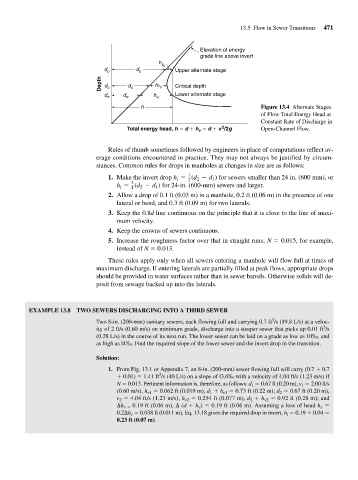
Elevation of energy
grade line above invert
h
v u
d u d u Upper alternate stage
Depth d c d c hv c Critical depth
d e d e h v i Lower alternate stage
h Figure 13.4 Alternate Stages
of Flow Total Energy Head at
Constant Rate of Discharge in
2
Total energy head, h d h d v /2g Open-Channel Flow.
v
Rules of thumb sometimes followed by engineers in place of computations reflect av-
erage conditions encountered in practice. They may not always be justified by circum-
stances. Common rules for drops in manholes at changes in size are as follows:
1
1. Make the invert drop h = 2 (d - d ) for sewers smaller than 24 in. (600 mm), or
1
2
i
3
h = 4 (d - d ) for 24-in. (600-mm) sewers and larger.
2
1
i
2. Allow a drop of 0.1 ft (0.03 m) in a manhole, 0.2 ft (0.06 m) in the presence of one
lateral or bend, and 0.3 ft (0.09 m) for two laterals.
3. Keep the 0.8d line continuous on the principle that it is close to the line of maxi-
mum velocity.
4. Keep the crowns of sewers continuous.
5. Increase the roughness factor over that in straight runs; N 0.015, for example,
instead of N 0.013.
These rules apply only when all sewers entering a manhole will flow full at times of
maximum discharge. If entering laterals are partially filled at peak flows, appropriate drops
should be provided in water surfaces rather than in sewer barrels. Otherwise solids will de-
posit from sewage backed up into the laterals.
EXAMPLE 13.8 TWO SEWERS DISCHARGING INTO A THIRD SEWER
3
Two 8-in. (200-mm) sanitary sewers, each flowing full and carrying 0.7 ft /s (19.8 L/s) at a veloc-
3
ity of 2 ft/s (0.60 m/s) on minimum grade, discharge into a steeper sewer that picks up 0.01 ft /s
(0.28 L/s) in the course of its next run. The lower sewer can be laid on a grade as low as 10‰, and
as high as l4‰. Find the required slope of the lower sewer and the invert drop in the transition.
Solution:
1. From Fig. 13.1 or Appendix 7, an 8-in. (200-mm) sewer flowing full will carry (0.7 0.7
3
0.01) 1.41 ft /s (40 L/s) on a slope of l3.6‰ with a velocity of 4.04 ft/s (1.23 m/s) if
N 0.013. Pertinent information is, therefore, as follows: d 1 0.67 ft (0.20 m), v 1 2.00 ft/s
(0.60 m/s), h v1 0.062 ft (0.019 m), d 1 h v1 0.73 ft (0.22 m); d 2 0.67 ft (0.20 m),
v 2 4.04 ft/s (1.23 m/s), h v2 0.254 ft (0.077 m), d 2 h v2 0.92 ft (0.28 m); and
h v 0.19 ft (0.06 m), (d h v ) 0.19 ft (0.06 m). Assuming a loss of head h e
0.2 h v 0.038 ft (0.011 m), Eq. 13.18 gives the required drop in invert, h i 0.19 0.04
0.23 ft (0.07 m).