
Page 527 - Fair, Geyer, and Okun's Water and wastewater engineering : water supply and wastewater removal
P. 527
JWCL344_ch13_457-499.qxd 8/7/10 8:49 PM Page 485
13.10 Street Inlets 485
= 1 - (1 - 0.62) 2.67
= 1 - (0.38) 2.67
= 1 - 0.075
0.925; that is, 92.5%
Q w QE 0
3
3
Q w 1ft /s 0.925 0.92 ft /s (26 L/s)
3
The gutter flow contained in the width of the grate inlet is 0.92 ft /s (26 L/s).
Solution 2 (SI System):
E 0 = 1 - (1 - W g >T) 2.67
E 0 = 1 - (1 - 0.61>0.98) 2.67
= 0.925; that is, 92.5%
Q w = QE 0
3
3
Q w = (0.0283 m /s) * 0.925 = 0.026 m /s (26 L/s)
3
The gutter flow contained in the width of the grate inlet is 0.026 m /s or 26 L/s.
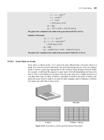
13.10.2 Grate Inlets on Grade
Grate inlets, as shown in Fig. 13.13, tend to be more efficient than curb inlets when on a
grade. Two concerns must be addressed in the grate inlet design process. First, the engineer
needs to choose a grate type appropriate for the roadway being designed. Bicycle traffic,
for example, would limit the engineer to grate types with both longitudinal and transverse
bars in order to prevent bicycle accidents. Second, grate inlets have a higher propensity to
clog than other types of inlets. If debris is prevalent in runoff at the point of design, ade-
quate provisions must be made to account for inlet clogging, such as utilizing a combina-
tion (grate and curb) inlet at these points.
W
L
Reticuline
P-50mm P-50mm × 100 mm
Figure 13.13 Grate Inlet in a Gutter and Some Typical Grate Types.