
Page 522 - Fair, Geyer, and Okun's Water and wastewater engineering : water supply and wastewater removal
P. 522
JWCL344_ch13_457-499.qxd 8/7/10 8:49 PM Page 480
480 Chapter 13 Hydraulics of Sewer Systems
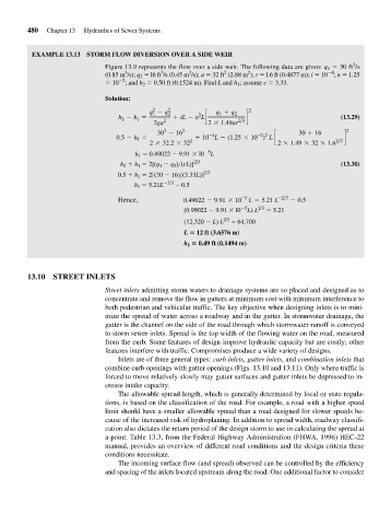
EXAMPLE 13.13 STORM FLOW DIVERSION OVER A SIDE WEIR
3
Figure 13.9 represents the flow over a side weir. The following data are given: q 1 30 ft /s
3
2
3
3
4
2
(0.85 m /s); q 2 l6 ft /s (0.45 m /s); a 32 ft (2.88 m ); r l.6 ft (0.4877 m); i 10 ; n 1.25
2
10 ; and h 2 0.50 ft (0.1524 m). Find L and h 1 ; assume c 3.33.
Solution:
2 2 2
q 1 - q 2 2 q 1 + q 2
h 2 - h 1 = + iL - n Lc d (13.29)
2ga 2 2 * 1.49ar 2>3
2
30 - 16 2 -4 -2 2 30 + 16 2
0.5 - h 1 = + 10 L - (1.25 * 10 ) L c d
2 * 32.2 * 32 2 2 * 1.49 * 32 * 1.6 2>3
5
h 1 0.49022 9.91 l0 L
h 2 h 1 2[(q 1 q 2 )>(cL)] 2/3 (13.30)
0.5 h 1 2[(30 16)>(3.33L)] 2/3
h 1 5.21L 2/3 0.5
Hence, 0.49022 - 9.91 * 10 -5 L = 5.21 L -2>3 - 0.5
5
(0.99022 9.91 l0 L) L 2/3 5.21
(12,320 L) L 2/3 64,700
L 12 ft (3.6576 m)
h 1 0.49 ft (0.1494 m)
13.10 STREET INLETS
Street inlets admitting storm waters to drainage systems are so placed and designed as to
concentrate and remove the flow in gutters at minimum cost with minimum interference to
both pedestrian and vehicular traffic. The key objective when designing inlets is to mini-
mize the spread of water across a roadway and in the gutter. In stormwater drainage, the
gutter is the channel on the side of the road through which stormwater runoff is conveyed
to storm sewer inlets. Spread is the top width of the flowing water on the road, measured
from the curb. Some features of design improve hydraulic capacity but are costly; other
features interfere with traffic. Compromises produce a wide variety of designs.
Inlets are of three general types: curb inlets, gutter inlets, and combination inlets that
combine curb openings with gutter openings (Figs. 13.10 and 13.11). Only where traffic is
forced to move relatively slowly may gutter surfaces and gutter inlets be depressed to in-
crease intake capacity.
The allowable spread length, which is generally determined by local or state regula-
tions, is based on the classification of the road. For example, a road with a higher speed
limit should have a smaller allowable spread than a road designed for slower speeds be-
cause of the increased risk of hydroplaning. In addition to spread width, roadway classifi-
cation also dictates the return period of the design storm to use in calculating the spread at
a point. Table 13.3, from the Federal Highway Administration (FHWA, 1996) HEC-22
manual, provides an overview of different road conditions and the design criteria these
conditions necessitate.
The incoming surface flow (and spread) observed can be controlled by the efficiency
and spacing of the inlets located upstream along the road. One additional factor to consider