Page 521 - Fair, Geyer, and Okun's Water and wastewater engineering : water supply and wastewater removal
P. 521

JWCL344_ch13_457-499.qxd  8/7/10  8:49 PM  Page 479


                                                                                 13.9 Bends, Junctions, and Overfalls  479
                    13.9  BENDS, JUNCTIONS, AND OVERFALLS

                                         In common with many other uncertainties of fluid behavior in hydraulic systems, head
                                                                                                     2
                                         losses in bends are often approximated as functions of the velocity head v /2g. For small
                                         sewers, the radius of an optimal circular curve of the center line of the sewer is reported to
                                         be three to six times the sewer diameter.
                                             The conjoining of the flow patterns of two or more sewers normally involves curva-
                                         ture as well as impact effects. Generalization of resulting head losses is difficult. Where
                                         predictions of surface profiles are important, in the case of large sewers, for example,
                                         model studies are advisable. Otherwise, the usual procedure of working upstream from a
                                         known point, especially a control point, should identify the water surface profile reason-
                                         ably well.
                                             Storm flows in excess of interceptor capacity are often diverted into natural drainage
                                         channels through overfalls or side weirs. Needed weir lengths depend on the general di-
                                         mensions and hydraulic characteristics of the sewer and the nature and orientation of the
                                         weir itself. Understandably, side weirs paralleling the direction of flow must be longer than
                                         weirs at right angles to it.
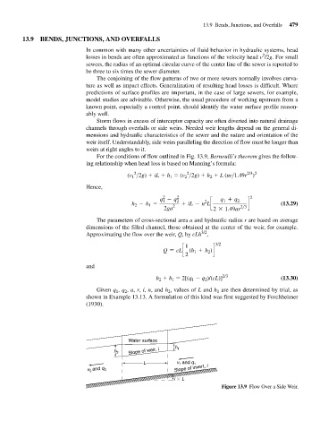
                                             For the conditions of flow outlined in Fig. 13.9, Bernoulli’s theorem gives the follow-
                                          ing relationship when head loss is based on Manning’s formula:
                                                                            2
                                                          2
                                                                                                2/3 2
                                                        (v 1 >2g)   iL   h 1   (v 2 >2g)   h 2   L (nv>1.49r )
                                         Hence,
                                                                    2
                                                                   q - q 2 2           q + q 2   2
                                                                    1
                                                                                        1
                                                                                  2
                                                         h - h =       2  + iL - n Lc           d           (13.29)
                                                               1
                                                          2
                                                                    2ga              2 * 1.49ar 2>3
                                             The parameters of cross-sectional area a and hydraulic radius r are based on average
                                         dimensions of the filled channel, those obtained at the center of the weir, for example.
                                                                                 3/2
                                         Approximating the flow over the weir, Q, by cLh ,
                                                                           1         3/2
                                                                    Q = cLc   (h + h )d
                                                                              1
                                                                                   2
                                                                           2
                                         and
                                                                 h 2   h 1   2[(q 1   q 2 )/(cL)] 2/3       (13.30)
                                             Given q 1 , q 2 , a, r, i, n, and h 2 , values of L and h 1 are then determined by trial, as
                                         shown in Example 13.13. A formulation of this kind was first suggested by Forchheimer
                                         (1930).


                                                        Water surface

                                                   h 2  Slope of weir, i  h 1
                                                             L          v and q 1
                                                                         1
                                          v 2  and q 2                  Slope of invert, i
                                                                       i   L
                                                                                        Figure 13.9 Flow Over a Side Weir.
   516   517   518   519   520   521   522   523   524   525   526