
Page 86 - Fair, Geyer, and Okun's Water and wastewater engineering : water supply and wastewater removal
P. 86
JWCL344_ch02_029-060.qxd 8/2/10 9:14 PM Page 49
2.10 Dams and Dikes 49
from washing away, it is commonly seeded with grass or covering vines and provided with a
system of surface and subsurface drains. Berms break up the face into manageable drainage
areas and give access to slopes for mowing and maintenance. Although they are more or less
horizontal, berms do slope inward to gutters; moreover, they are pitched lengthwise for the
gutters to conduct runoff to surface or subsurface main drains and through them safely down
the face or abutment of the dam, eventually into the stream channel.
Earth embankments are constructed either as rolled fills or hydraulic fills; rock embank-
ments are built as uncompacted (dumped) or compacted fills. In rolled earth fills, successive
layers of earth 4 to 12 in. (100 to 300 mm) thick are spread, rolled, and consolidated. Sheep’s-
foot rollers do the compacting, but they are helped in their work by heavy earth-moving vehi-
cles bringing fill to the dam or bulldozing it into place. Portions of embankment that cannot be
rolled in this way are compacted by hand or power tampers. Strips adjacent to concrete core
walls, the walls of outlet structures, and the wingwalls of spillway sections are examples.
In hydraulic fills water-carried soil is deposited differentially to form an embankment
graded from coarse at the two faces of the dam to fine in the central core.
Methods as well as materials of construction determine the strength, tightness, and
stability of embankment dams. Whether their axis should be straight or curved depends
largely on topographic conditions. Whether upstream curves are in fact useful is open to
question. The intention is to provide axial compression in the core and prevent cracks as
the dam settles. Spillways are incorporated into some embankment dams and divorced
from others in separate constructions.
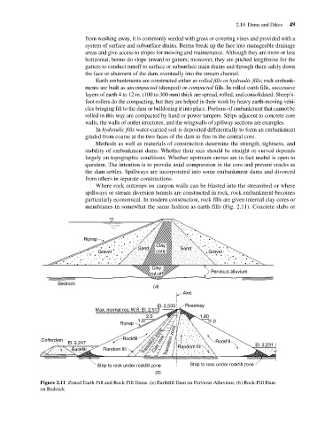
Where rock outcrops on canyon walls can be blasted into the streambed or where
spillways or stream diversion tunnels are constructed in rock, rock embankment becomes
particularly economical. In modern construction, rock fills are given internal clay cores or
membranes in somewhat the same fashion as earth fills (Fig. 2.11). Concrete slabs or
Riprap
Clay
Sand Sand
Gravel core Gravel
Clay
cut-off Pervious alluvium
Bedrock
(a)
Axis
El. 2,533 Roadway
Max. normal res. W.S. El. 2,513
2.0 1.80
1.0 1.0
Riprap
Transition zone Rockfill
Cofferdam Rockfill Transition zone
El. 2,247 Clay core El. 2,231
Backfill Random fill Random fill
Strip to rock under rockfill zone Strip to rock under rockfill zone
(b)
Figure 2.11 Zoned Earth-Fill and Rock-Fill Dams. (a) Earthfill Dam on Pervious Alluvium; (b) Rock-Fill Dam
on Bedrock.