
Page 90 - Fair, Geyer, and Okun's Water and wastewater engineering : water supply and wastewater removal
P. 90
JWCL344_ch02_029-060.qxd 8/2/10 9:14 PM Page 53
2.12 Intakes 53
Washwater
Pump discharge discharge
Backwash inlet
Bar rack
1–2-in. Outer
spacing
casing
Flow Wet Inner
well
Sectional plan casing
of intake cowl
Pump
column
Well screen
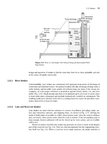
Figure 2.14 River or Lake Intake with Vertical Pump and Backwashed Well-
Type Screen
design and operation of intakes is that the water they draw be as clean, palatable, and safe
as the source of supply can provide.
2.12.1 River Intakes
Understandably, river intakes are constructed well upstream from points of discharge of
wastewater and industrial wastes. An optimal location will take advantage of deep water, a
stable bottom, and favorable water quality (if pollution hugs one shore of the stream, for
example), all with proper reference to protection against floods, debris, ice, and river
traffic (Fig. 2.14). Small streams may have to be dammed up by diversion or intake dams
to keep intake pipes submerged and preclude hydraulically wasteful air entrainment. The
resulting intake pool will also work well as a settling basin for coarse silt and allow a pro-
tective sheet of ice to form in winter.
2.12.2 Lake and Reservoir Intakes
Lake intakes are sited with due reference to sources of pollution, prevailing winds, sur-
face and subsurface currents, and shipping lanes. As shown in Fig. 2.15, shifting the
depth of draft makes it possible to collect clean bottom water when the wind is offshore
and, conversely, clean surface water when the wind is onshore. If the surrounding water is
deep enough, bottom sediments will not be stirred up by wave action, and ice troubles
will be few.
Reservoir intakes resemble lake intakes but generally lie closer to shore in the deepest
part of the reservoir (see Fig. 2.6). They are often incorporated into the impounding struc-
ture itself (see Fig. 2.4). Where a reservoir serves many purposes, the intake structure is