
Page 89 - Fair, Geyer, and Okun's Water and wastewater engineering : water supply and wastewater removal
P. 89
JWCL344_ch02_029-060.qxd 8/2/10 9:14 PM Page 52
52 Chapter 2 Water Sources: Surface Water
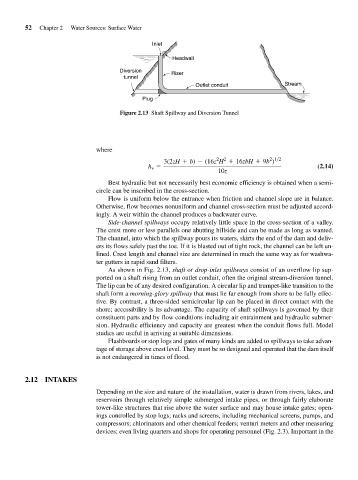
Inlet
Headwall
Diversion Riser
tunnel
Outlet conduit Stream
Plug
Figure 2.13 Shaft Spillway and Diversion Tunnel
where
2 2
2 1>2
3(2zH + b) - (16z H + 16zbH + 9b )
h = (2.14)
v
10z
Best hydraulic but not necessarily best economic efficiency is obtained when a semi-
circle can be inscribed in the cross-section.
Flow is uniform below the entrance when friction and channel slope are in balance.
Otherwise, flow becomes nonuniform and channel cross-section must be adjusted accord-
ingly. A weir within the channel produces a backwater curve.
Side-channel spillways occupy relatively little space in the cross-section of a valley.
The crest more or less parallels one abutting hillside and can be made as long as wanted.
The channel, into which the spillway pours its waters, skirts the end of the dam and deliv-
ers its flows safely past the toe. If it is blasted out of tight rock, the channel can be left un-
lined. Crest length and channel size are determined in much the same way as for washwa-
ter gutters in rapid sand filters.
As shown in Fig. 2.13, shaft or drop-inlet spillways consist of an overflow lip sup-
ported on a shaft rising from an outlet conduit, often the original stream-diversion tunnel.
The lip can be of any desired configuration. A circular lip and trumpet-like transition to the
shaft form a morning-glory spillway that must lie far enough from shore to be fully effec-
tive. By contrast, a three-sided semicircular lip can be placed in direct contact with the
shore; accessibility is its advantage. The capacity of shaft spillways is governed by their
constituent parts and by flow conditions including air entrainment and hydraulic submer-
sion. Hydraulic efficiency and capacity are greatest when the conduit flows full. Model
studies are useful in arriving at suitable dimensions.
Flashboards or stop logs and gates of many kinds are added to spillways to take advan-
tage of storage above crest level. They must be so designed and operated that the dam itself
is not endangered in times of flood.
2.12 INTAKES
Depending on the size and nature of the installation, water is drawn from rivers, lakes, and
reservoirs through relatively simple submerged intake pipes, or through fairly elaborate
tower-like structures that rise above the water surface and may house intake gates; open-
ings controlled by stop logs; racks and screens, including mechanical screens, pumps, and
compressors; chlorinators and other chemical feeders; venturi meters and other measuring
devices; even living quarters and shops for operating personnel (Fig. 2.3). Important in the