Page 88 - Fair, Geyer, and Okun's Water and wastewater engineering : water supply and wastewater removal
P. 88

JWCL344_ch02_029-060.qxd  8/2/10  9:14 PM  Page 51


                                                                                                  2.11 Spillways  51


                                                                  b

                                                              Plan

                                                                        z
                                                                      1
                                                                                          2
                                                       b            b                 h    v /2g
                                                                                       v
                                                                                  h
                                                     h v
                                                    H                             d


                                                        Longitudinal section
                                                              (a)                               (b)
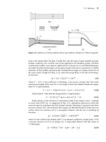
                                         Figure 2.12 Spillways (a) Channel Spillway and (b) Ogee Spillway. (Kindness of Arthur Casagrande)


                                         back to the stream below the dam. Usually they take the form of open channels and may
                                         include a relatively low overflow weir in the approach to the floodway proper. Overflow
                                         sections and overflow weirs must be calibrated if weir heads are to record flood discharges
                                         accurately, but their performance can be approximated from known calculations of similar
                                         structures. If their profile conforms to the ventilated lower nappe of a sharp-crested weir of
                                         the same relative height d>h (Fig. 2.12), under the design head, h, the rate of discharge,
                                          Q, becomes:
                                                                 Q   2>3c 22g  lh 3>2    Clh 3>2              (2.9)

                                         where C   2>3 c is the coefficient of discharge, g the gravity constant, and l the unob-
                                         structed crest length of the weir. For a crest height d above the channel bottom, the magni-
                                         tude of C is approximately:
                                                        C   4.15   0.65h>d for h>d 	 4 or C   4.15 to 6.75   (2.10)
                                             Under heads h
 other than the design head h, C approximates:
                                                            C   4.15(h
>h) 7>5  up to a ratio of h
>h   3.0  (2.11)

                                             If the entrance to the floodway is streamlined, little if any energy is lost—certainly
                                                          2
                                          no more than 0.05v >2g. As suggested in Fig. 2.12, substantial quiescence within the
                                         reservoir must be translated into full channel velocity. Discharge is greatest when flow
                                         becomes critical. The velocity head h then equals one-third the height H of the reservoir
                                         surface above the entrance sill to a rectangular channel, and the rate of discharge Q
                                         becomes:
                                                              Q   2>3CbH 22gH>3    3.087CbH 3>2              (2.12)

                                         where b is the width of the channel and C is an entrance coefficient varying from 1.0 for
                                         a smooth entrance to 0.8 for an abrupt one. A trapezoidal channel with side slopes of
                                         1:2 discharges:
                                                             Q   8.03Ch v 1>2  (H   h )[b   z(H   h )]       (2.13)
                                                                                            v
                                                                                v
   83   84   85   86   87   88   89   90   91   92   93