
Page 155 - Fiber Bragg Gratings
P. 155
132 Chapter 4 Theory of Fiber Bragg Gratings
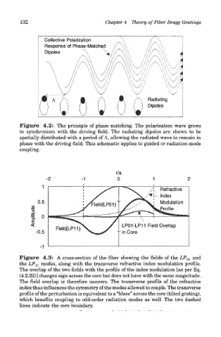
Figure 4.2: The principle of phase matching. The polarization wave grows
in synchronism with the driving field. The radiating dipoles are shown to be
spatially distributed with a period of A, allowing the radiated wave to remain in
phase with the driving field. This schematic applies to guided or radiation-mode
coupling.
Figure 4.3: A cross-section of the fiber showing the fields of the LP 01 and
the LP U modes, along with the transverse refractive index modulation profile.
The overlap of the two fields with the profile of the index modulation [as per Eq.
(4.2.22)] changes sign across the core but does not have with the same magnitude.
The field overlap is therefore nonzero. The transverse profile of the refractive
index thus influences the symmetry of the modes allowed to couple. The transverse
profile of the perturbation is equivalent to a "blaze" across the core (tilted grating),
which benefits coupling to odd-order radiation modes as well. The two dashed
lines indicate the core boundary.