
Page 159 - Fiber Bragg Gratings
P. 159
136 Chapter 4 Theory of Fiber Bragg Gratings
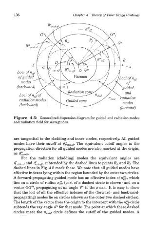
Figure 4.5: Generalized dispersion diagram for guided and radiation modes
and radiation field for waveguides.
are tangential to the cladding and inner circles, respectively. All guided
modes have their cutoff at 6^. iticai. The equivalent cutoff angles in the
propagation direction for all guided modes are also marked at the origin,
as
Cutoff-
For the radiation (cladding) modes the equivalent angles are
^critical an d % utoff> subtended by the dashed lines to points R b and Rf. The
dashed lines in Fig. 4.5 mark these. We note that all guided modes have
effective indexes lying within the region bounded by the outer two circles.
A forward-propagating guided mode has an effective index of n™ff, which
lies on a circle of radius n™fr (part of a dashed circle is shown) and on a
1
m
vector OG , propagating at an angle (T to the z-axis. It is easy to show
that the loci of all the effective indexes of the (forward- and backward-
propagating) modes lie on circles (shown as the outer two dashed circles).
1
The length of the vector from the origin to the intercept with the n ^ circle
71
subtends the ray angle ff for that mode. The point at which these dashed
circles meet the n clad circle defines the cutoff of the guided modes. A