
Page 163 - Fiber Bragg Gratings
P. 163
140 Chapter 4 Theory of Fiber Bragg Gratings
3
that for a standard fiber, with an n eff «* /i c/arf + 6An (<5rc = 4.5 X 10~ )
and b = 0.4 at 1550 nm [2], the angle at which the Bragg wavelength
equals the radiation wavelength is ff g *** 2.85°. It is clear from Eq. (4.2.35)
that the angle becomes larger with increasing core-cladding index differ-
ence.
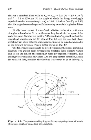
Finally there is a set of unconfined radiation modes at a continuum
of angles subtended at O, but with vector lengths within the space of the
radiation zone. Making the grating "effective index" n g small so that the
arrowhead remains on the RH side of Fig. 4.6, one can see that phase
matching will occur between copropagating modes, or to radiation modes
in the forward direction. This is better shown in Fig. 4.7.
The following points should be noted regarding the phase-matching
diagram. The guided mode propagation constants have discrete values
and lie on the loci for the particular mode propagation constants. The
grating vector can have any angle 6 g to the propagation direction, as can
the radiated field, provided the cladding is assumed to be at infinity. If,
Figure 4.7: The phase-matching diagram for copropagating modes with radi-
ation mode coupling with a long-period grating.